Practical BP 344 Compliance for Real Construction Projects
Design faster, avoid costly accessibility violations, and simplify Philippine compliance requirements with visual references built for architects, engineers, contractors, and project managers.
Avoid redesigns, failed inspections, accessibility violations, and costly construction corrections.
Visual references for Philippine accessibility compliance — covering accessible ramps, PWD parking, handrails & grab bars, corridors, accessible restrooms, elevators, doors & entrances, accessible routes, signage & wayfinding, and more — all aligned with the Amended IRR of Batas Pambansa Blg. 344 (Official Gazette, 2024).
Why BP 344 Compliance Matters
Failure to comply with BP 344 accessibility standards can lead to:
AEDO simplifies complex code requirements into practical visual references for actual construction implementation.
Deep Dive by Topic
Each standard has its own dedicated page with full provisions, key dimensions, diagrams, and FAQs.
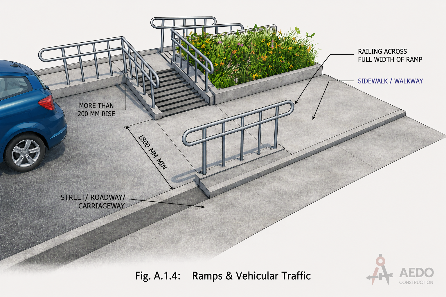
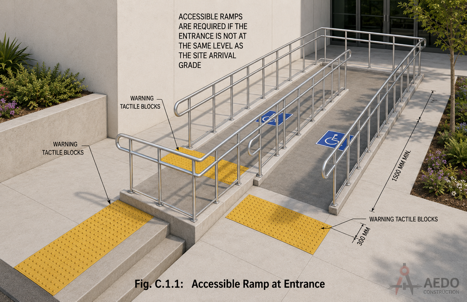
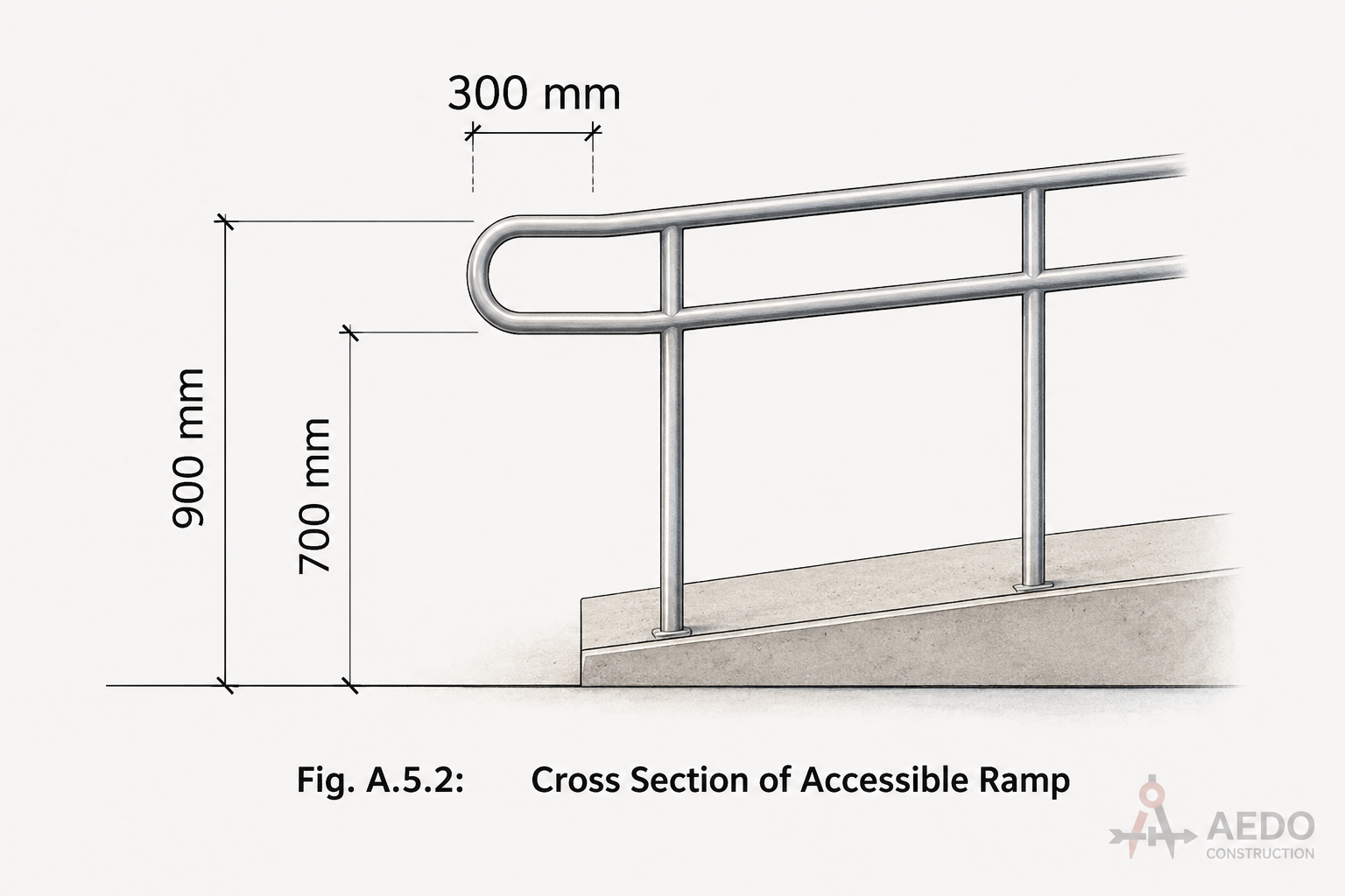
Accessible Ramps
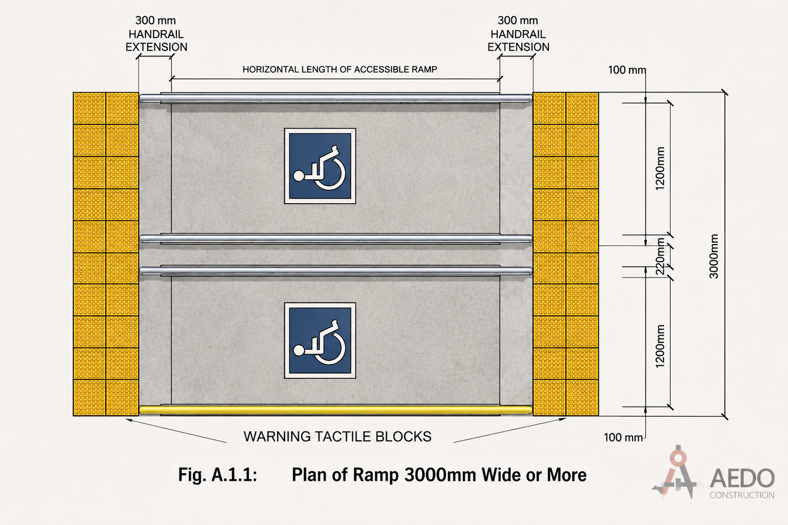
| Max Slope | Max Length | Max Rise | Landing Interval |
|---|---|---|---|
| 1:20 | — | — | 15 m |
| 1:15 | 10.50 m | 700 mm | 10 m |
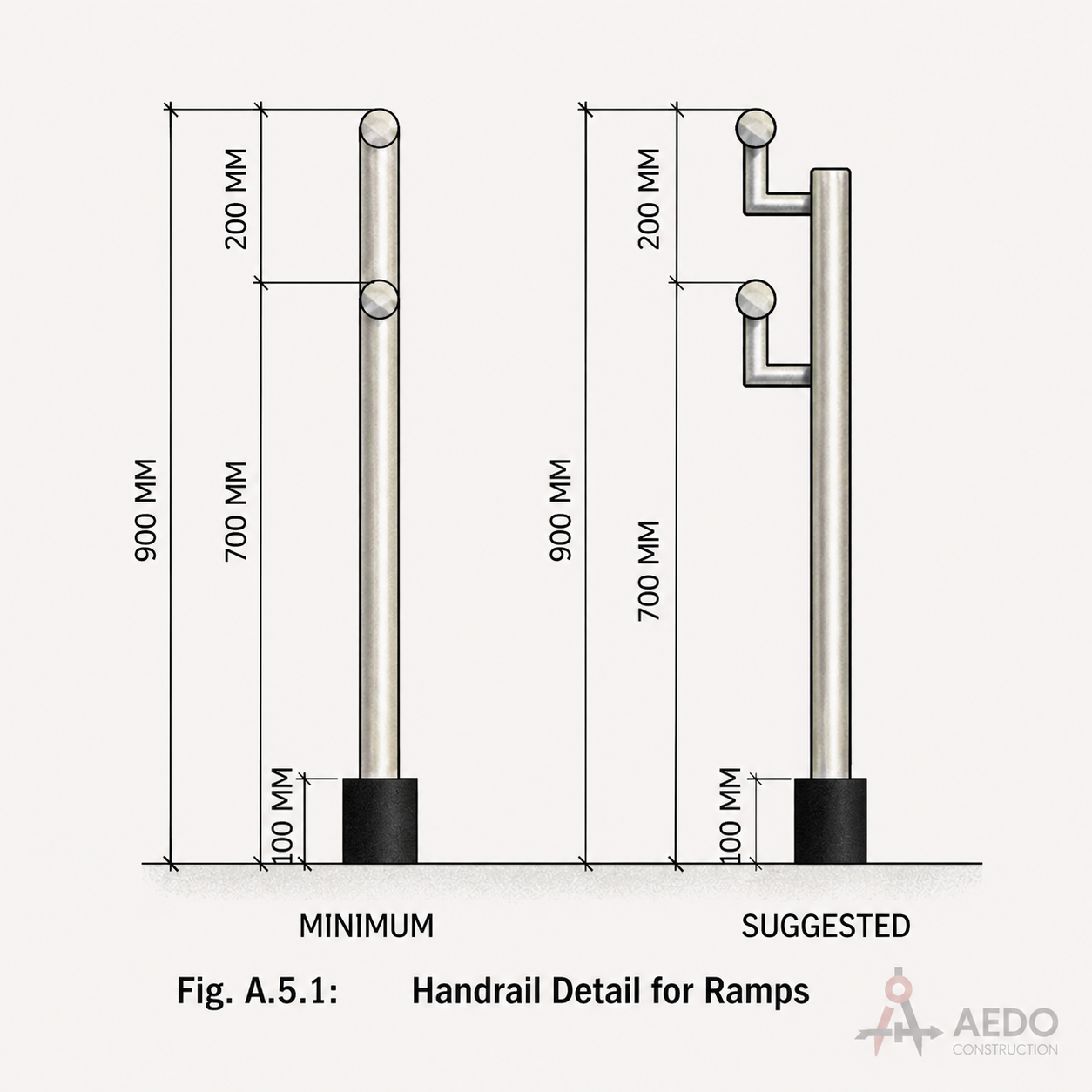
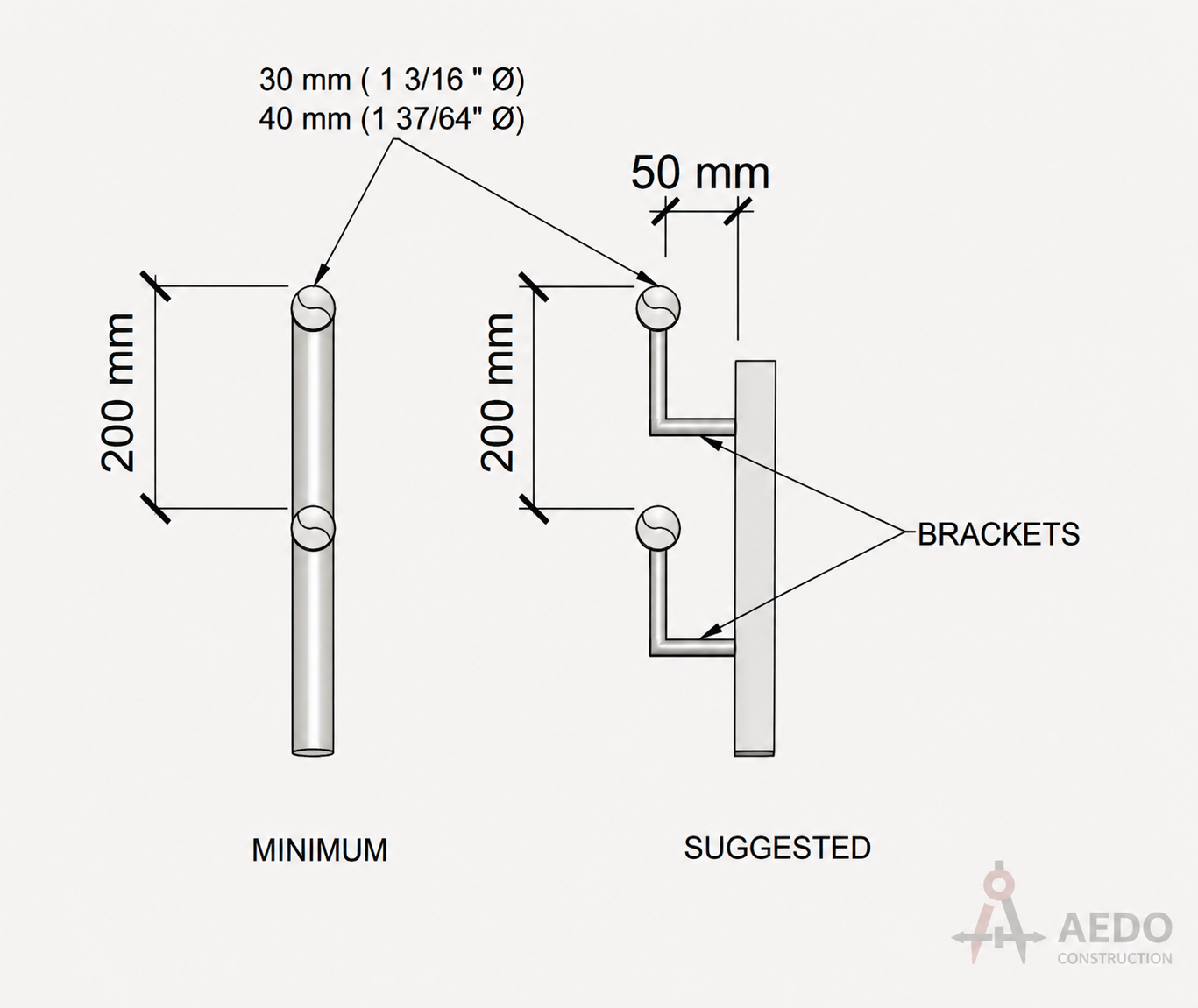
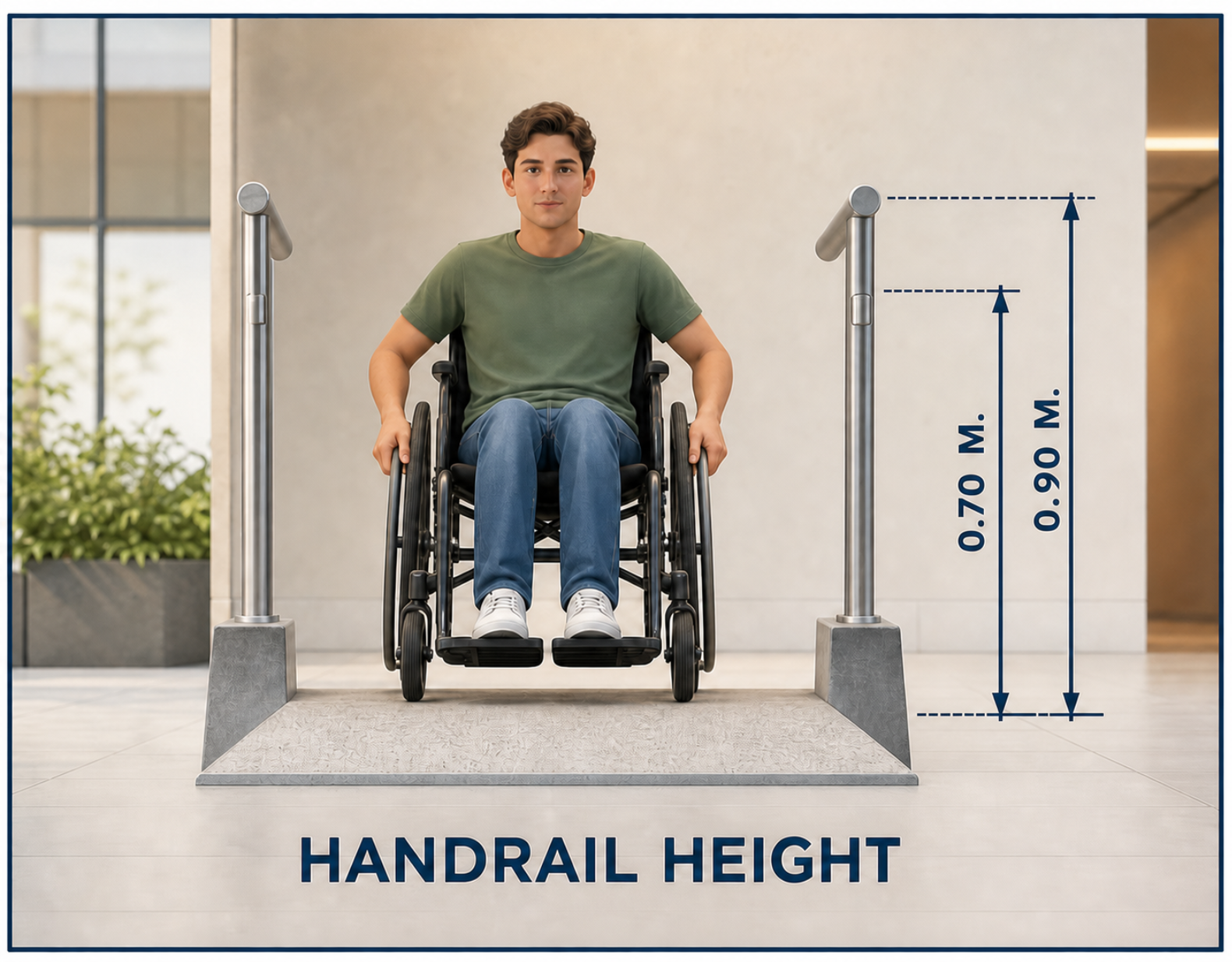
Handrails & Grab Bars
Accessible Parking
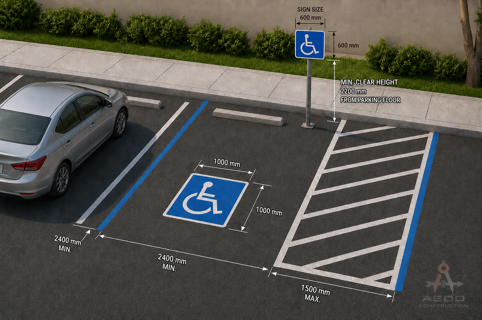
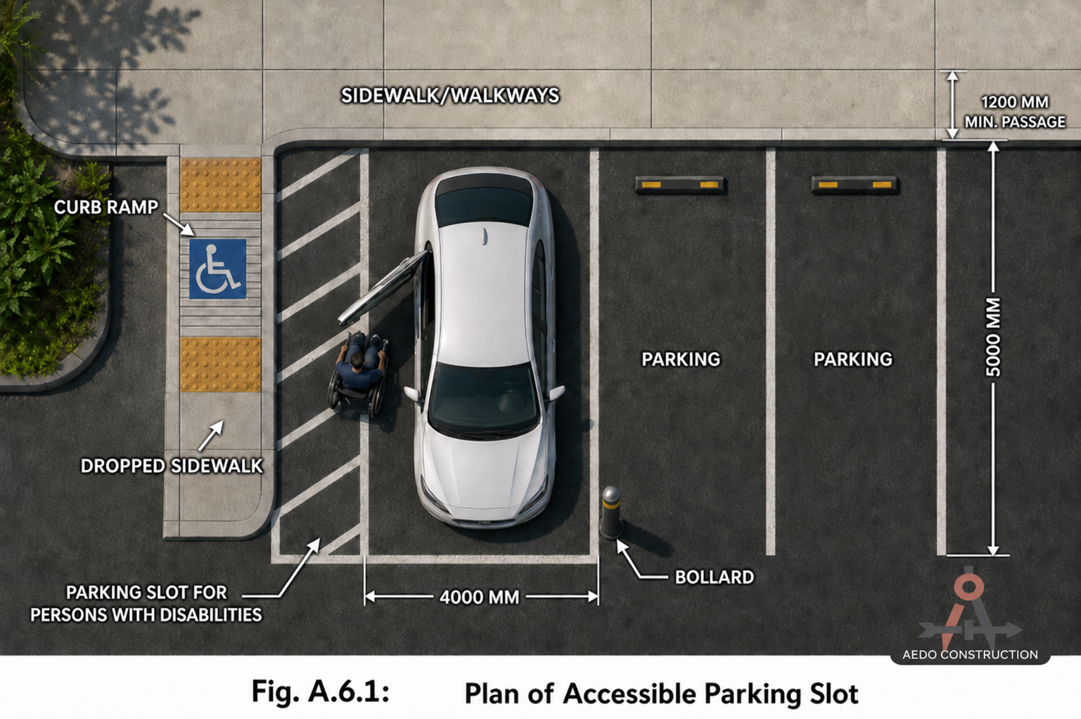
| Total Parking Slots | Required Accessible Slots |
|---|---|
| 1 – 25 | 1 |
| 26 – 50 | 2 |
| 51 – 75 | 3 |
| 76 – 100 | 4 |
| 101 – 150 | 5 |
| 151 – 200 | 6 |
| 201 – 300 | 7 |
| 301 – 400 | 8 |
| 401 – 500 | 9 |
| 501 – 1000 | 2% of Total |
| 1001 & Over | 20 + 1 per 100 over 1000 |
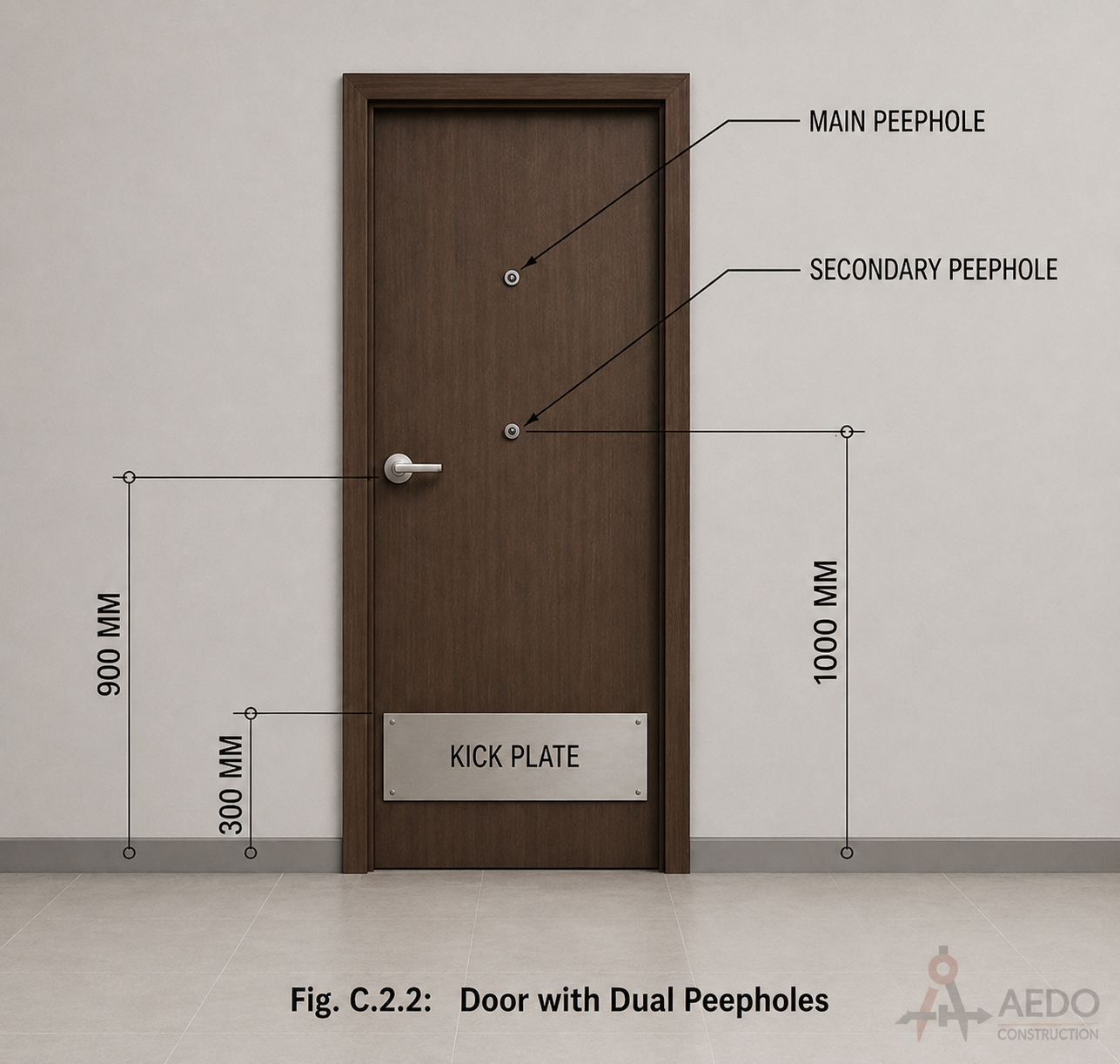
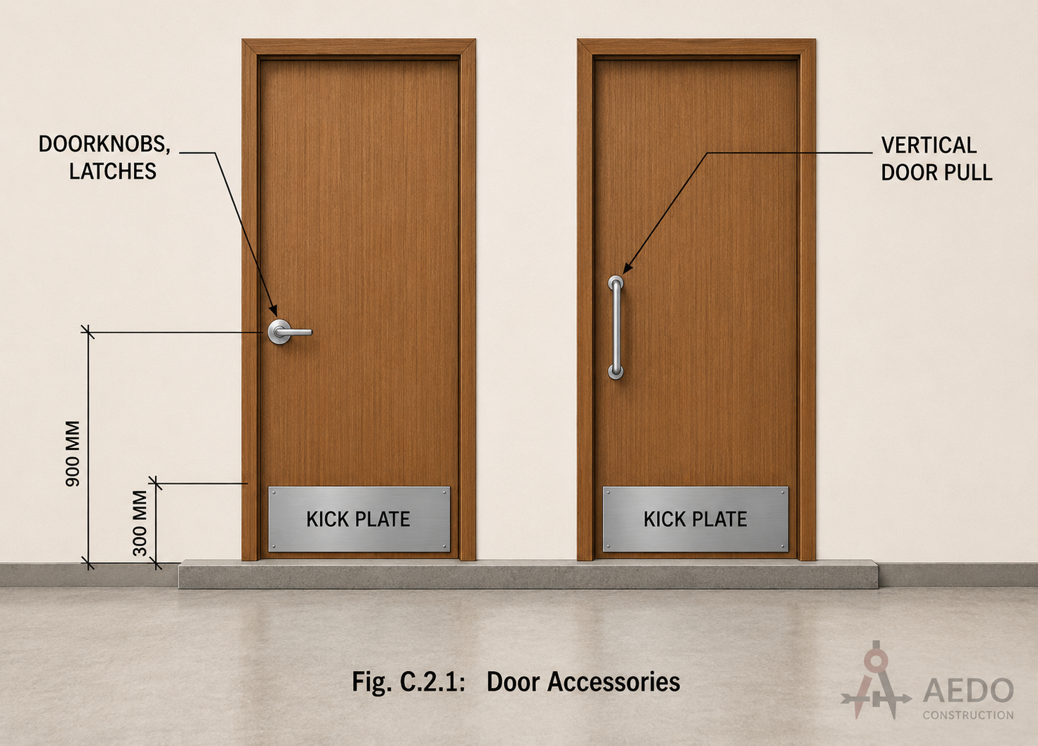
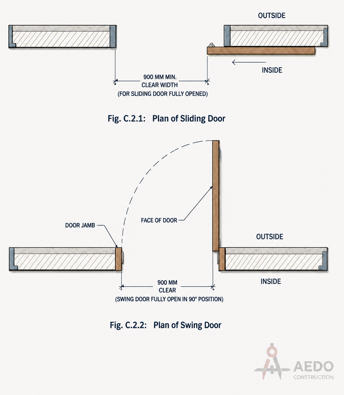
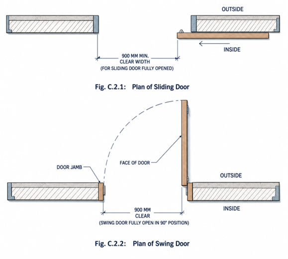
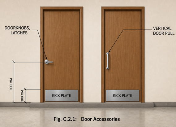
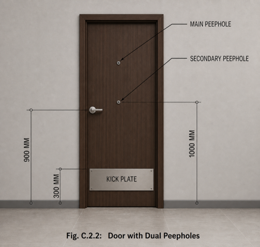
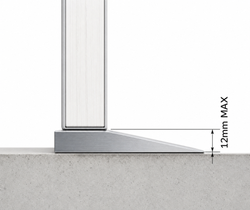
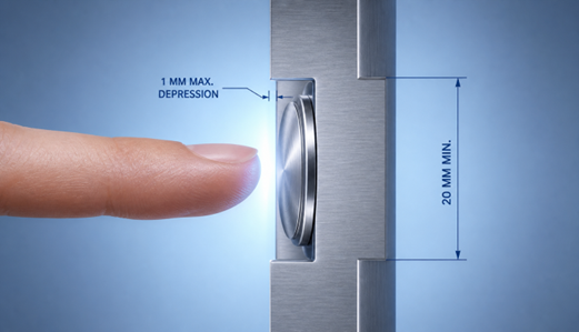
Doors & Entrances
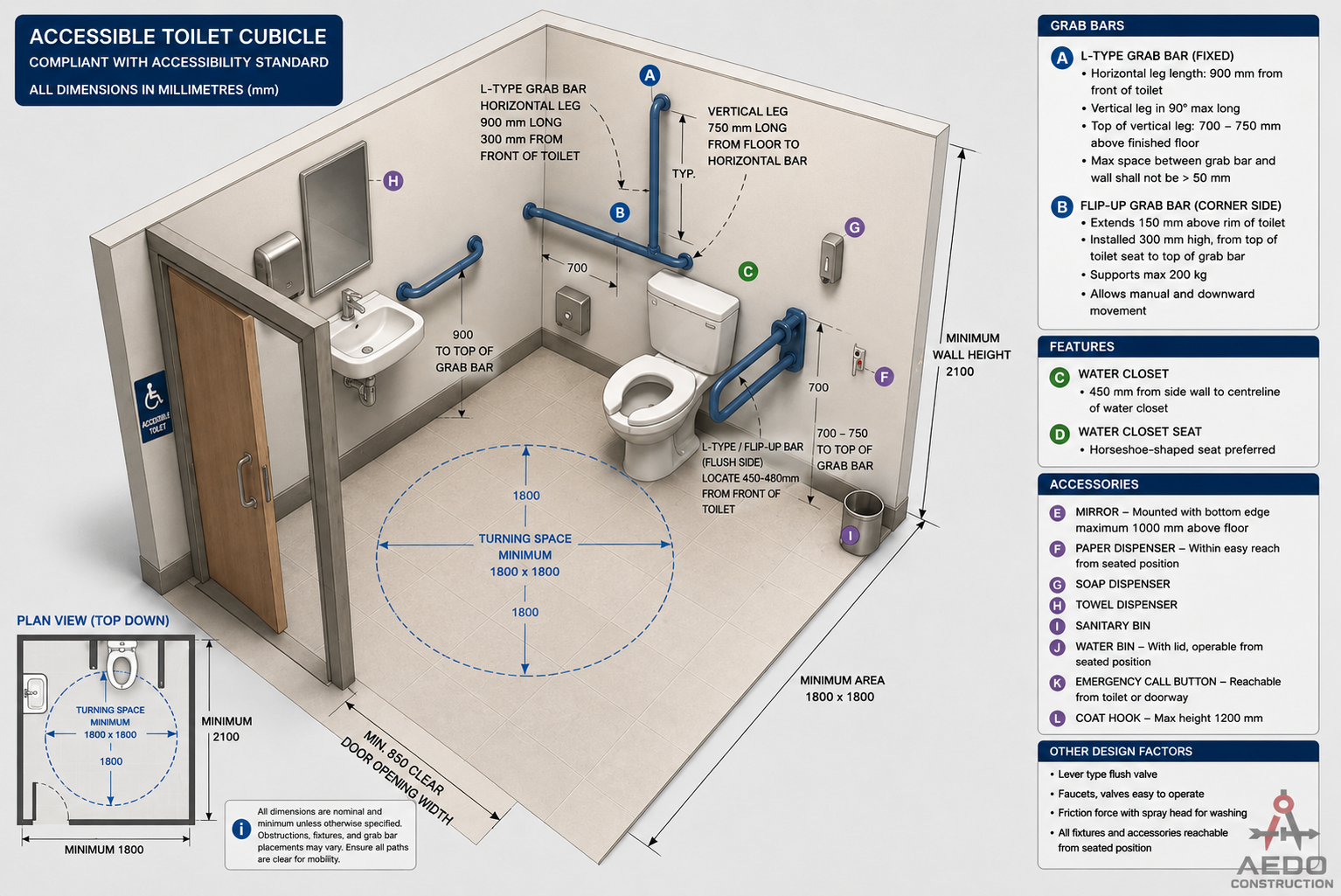
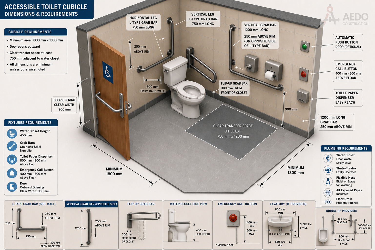
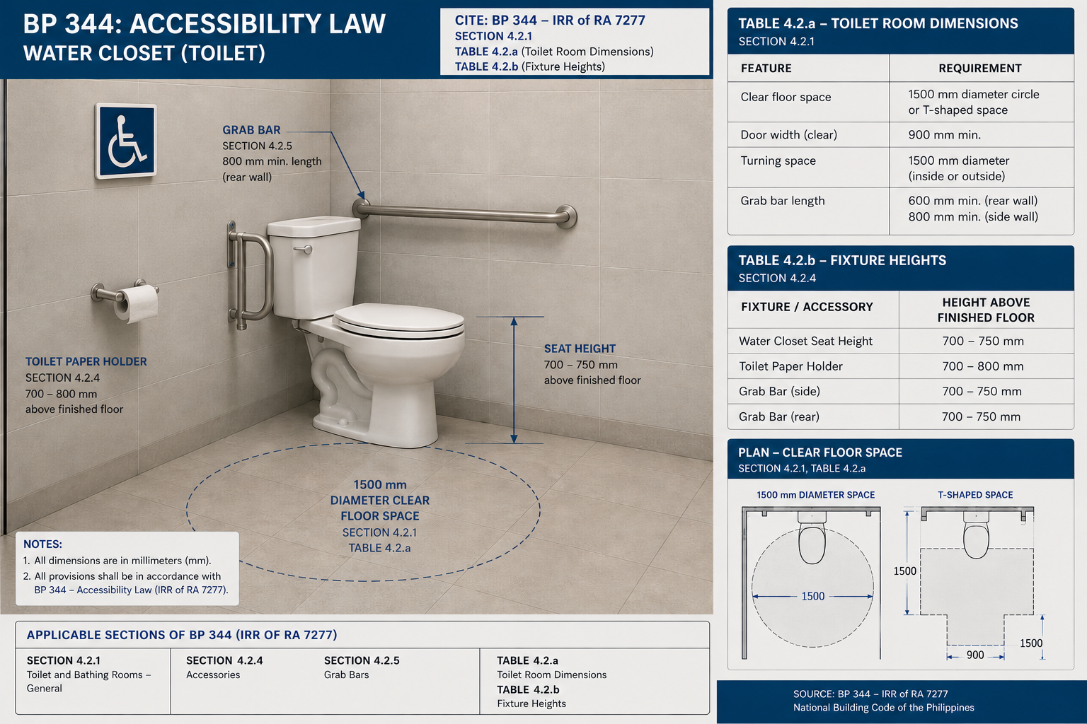
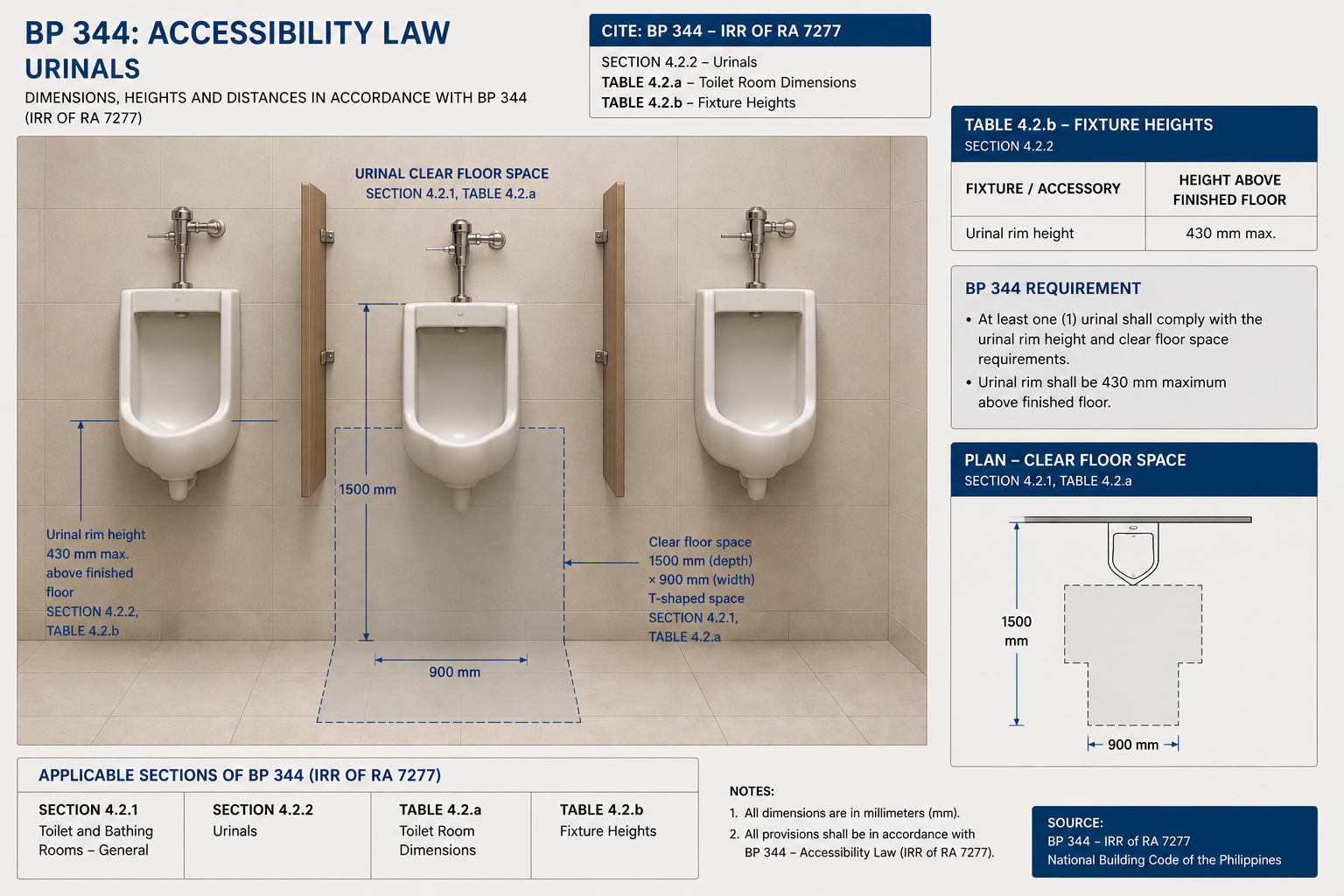
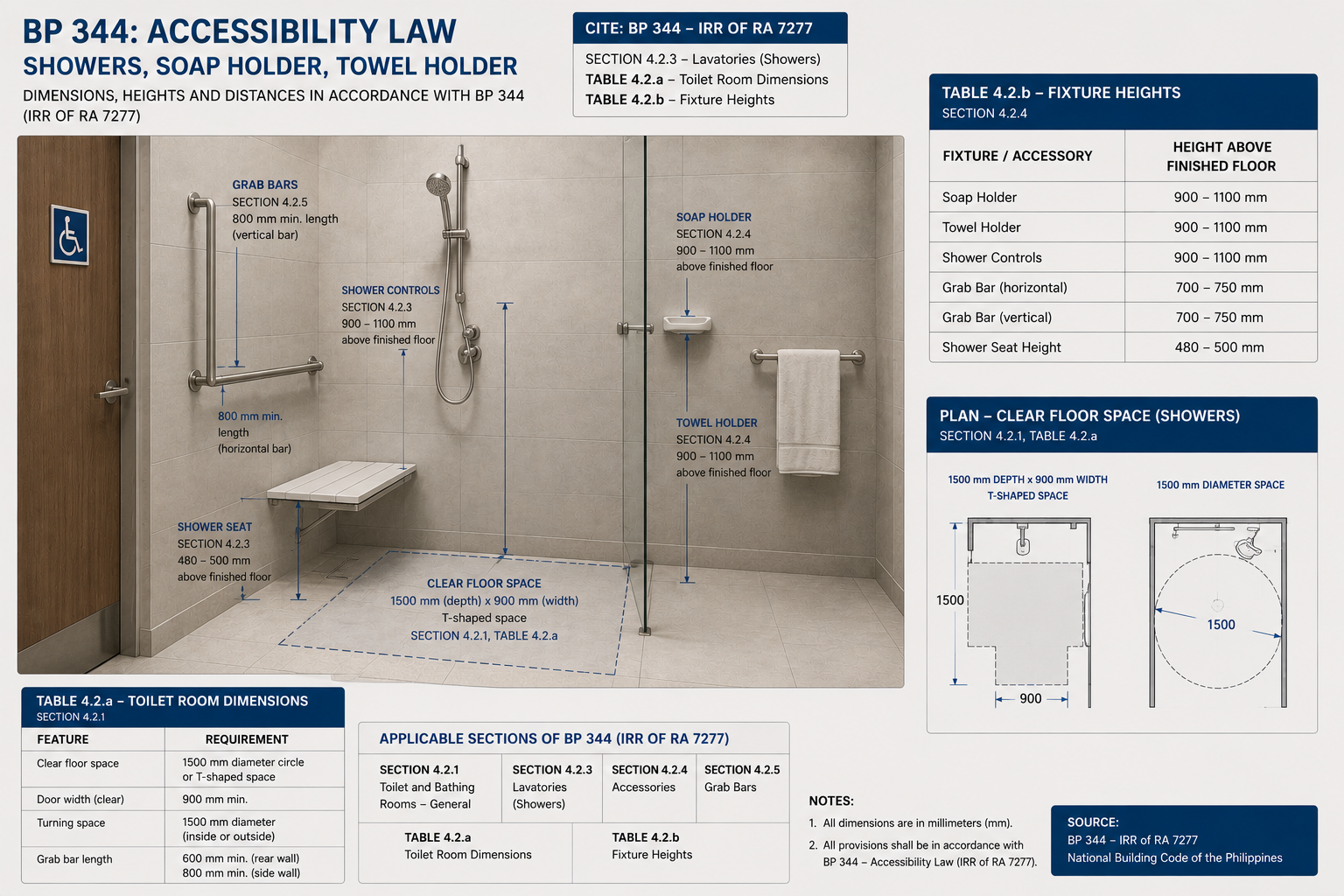
Toilets & Baths
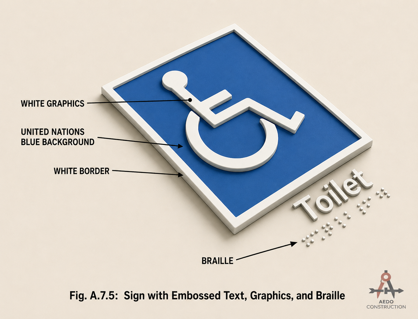
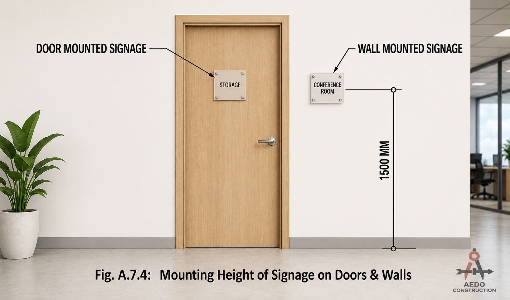
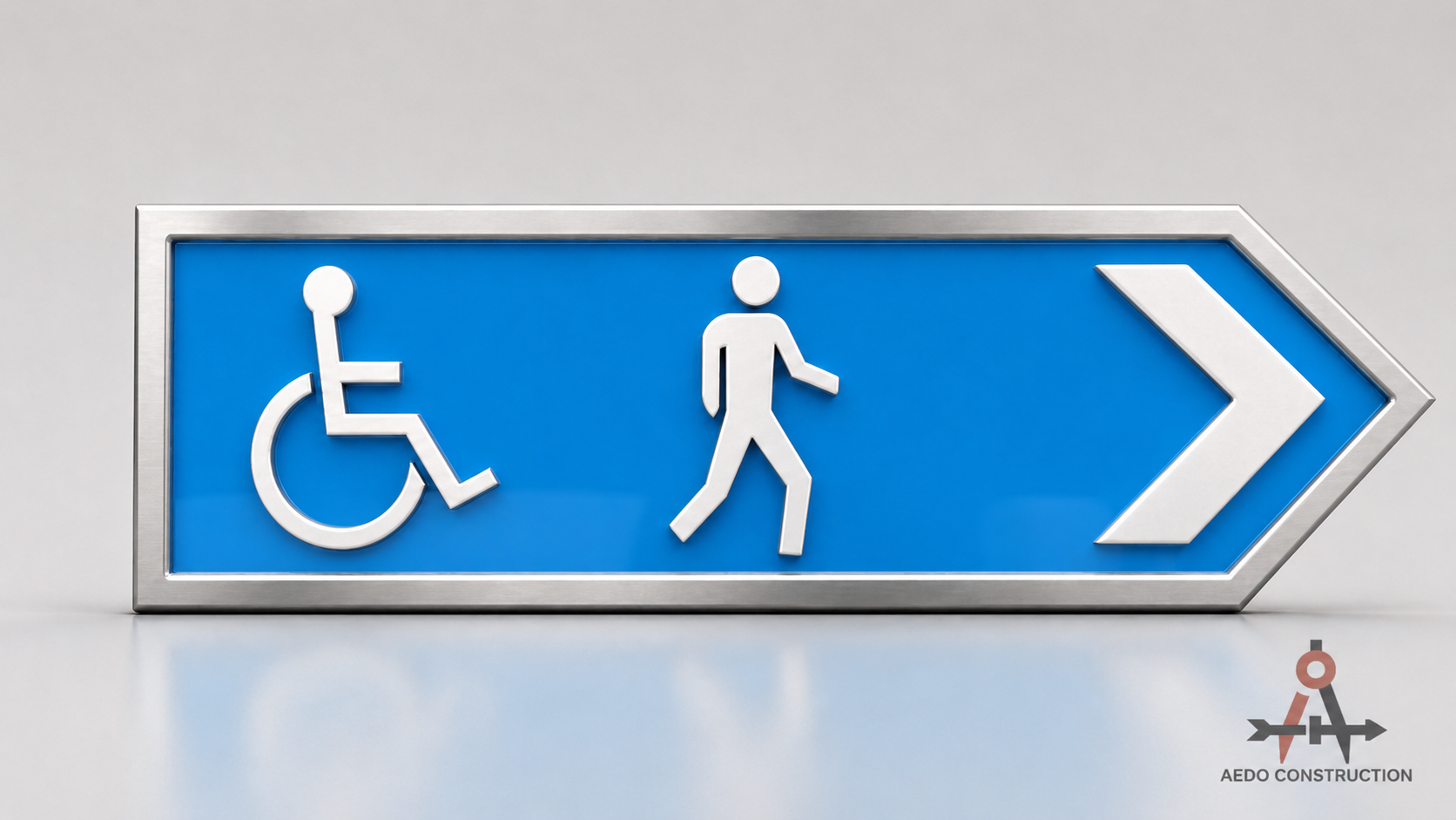
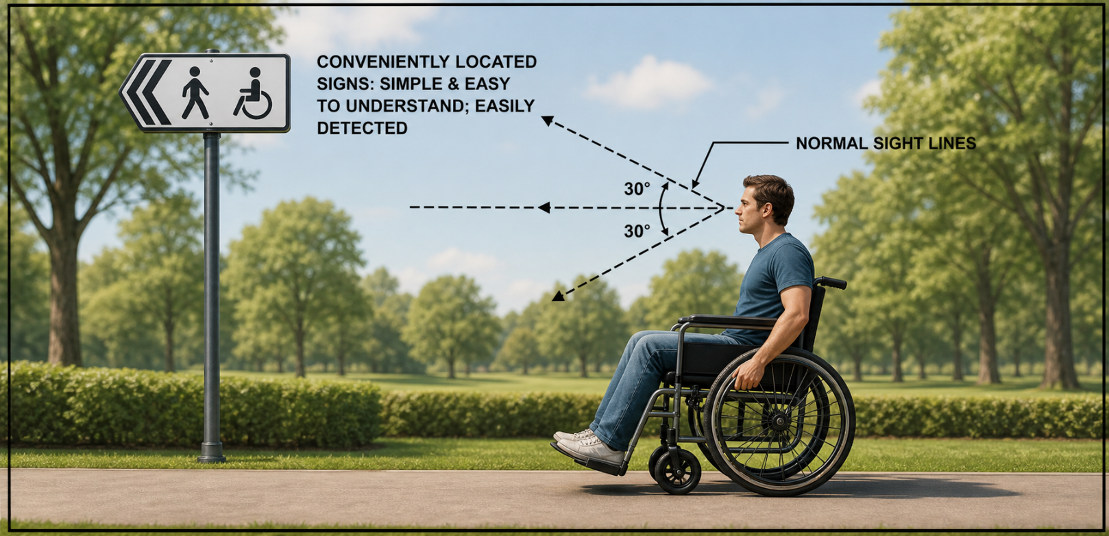
Signage & Wayfinding
| Viewing Distance | Symbol Size | Reading Distance | Min Letter Height |
|---|---|---|---|
| Up to 7.00 m | 60 × 60 mm | 1.0 m | 10 mm |
| 7.00 – 18.00 m | 100 × 100 mm | 3.0 m | 30 mm |
| Above 18.00 m | 200×200 – 450×400 mm | 5.0 m | 50 mm |
| — | — | 10.0 m | 100 mm |
| — | — | 20.0 m | 200 mm |
| — | — | 30.0 m | 300 mm |
| — | — | 50.0 m | 500 mm |
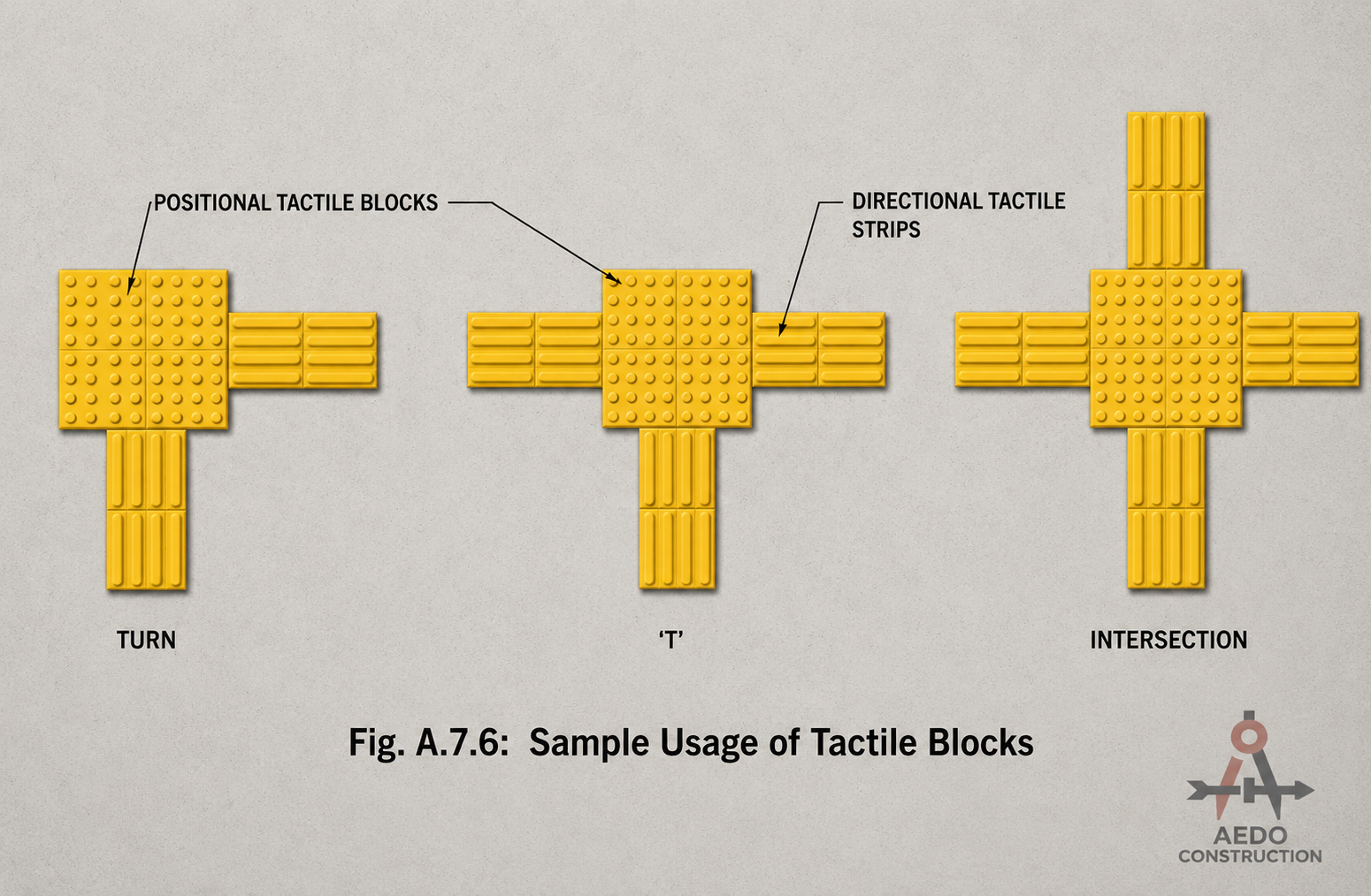
| Feature | Directional | Warning | Positional |
|---|---|---|---|
| Block Size | 300×300 mm | 300×300 mm | 300×300 mm |
| Orientation | Along travel direction | Perpendicular to travel | At direction changes |
| Min Count | At least 4 | At least 25 (5×5) | At least 25 (5×5) |
| Element Shape | Parallel raised bars | Truncated domes (grid) | Truncated domes (staggered) |
| Element Size | 34 mm wide bars | Ø 35 mm | Ø 23 mm |
| Raised Height | 5 mm | 5 mm | 5 mm |
| Type | Purpose | Pattern | Placement Rule |
|---|---|---|---|
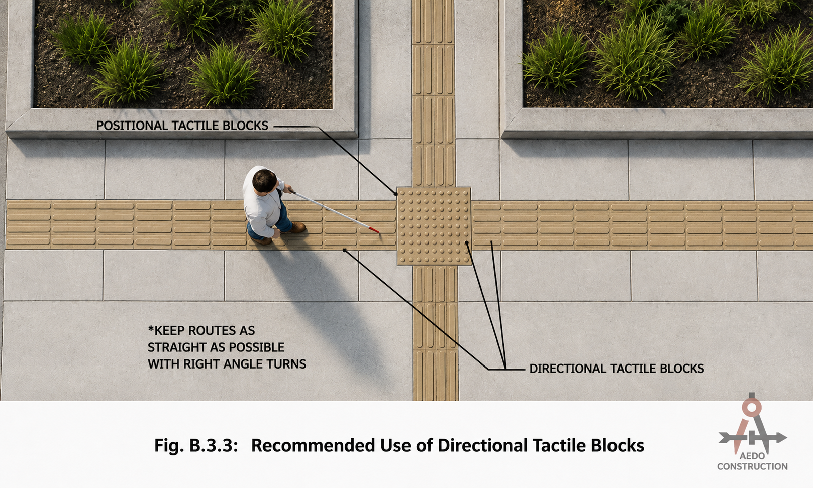
| Warning | Indicate hazards ahead & destinations with amenities | Grid pattern | Depth 600 mm; 300 mm setback from hazard/target |
| Positional | Indicate possible change in walking direction | Staggered pattern | At junctions to show change in travel direction |
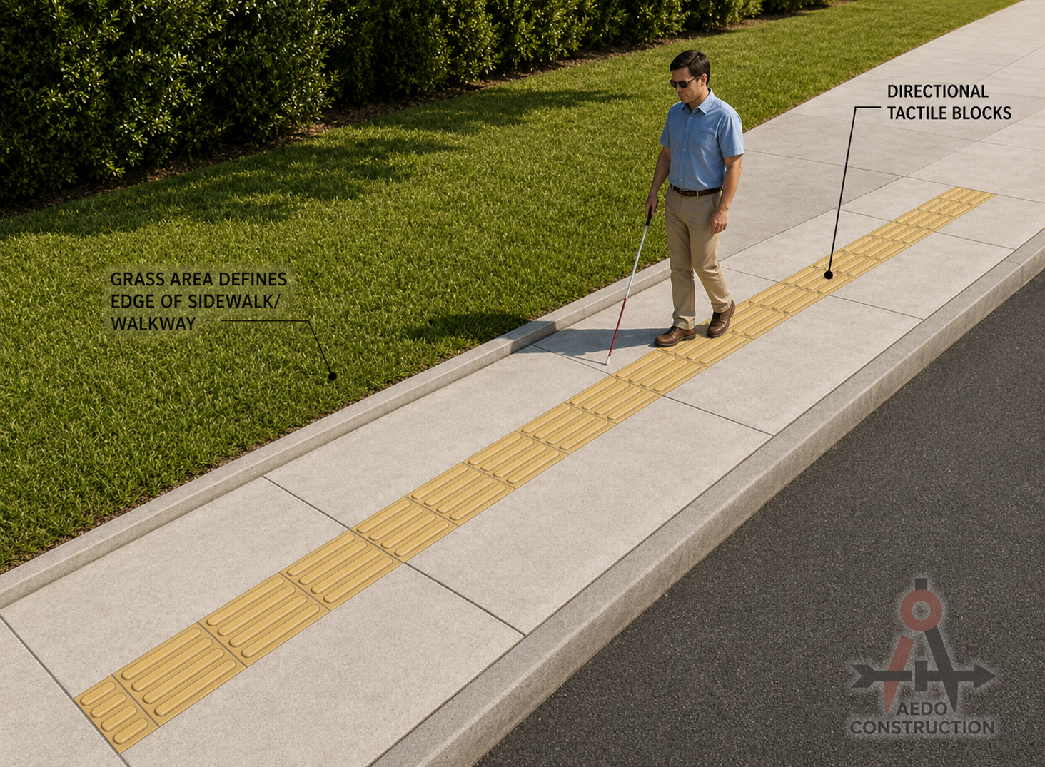
| Directional | Indicate safe intended path | Strip / bar pattern | Along centerline; single paths for two-way traffic |
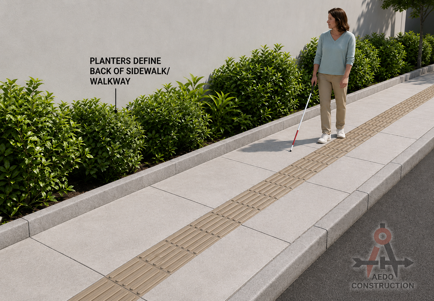
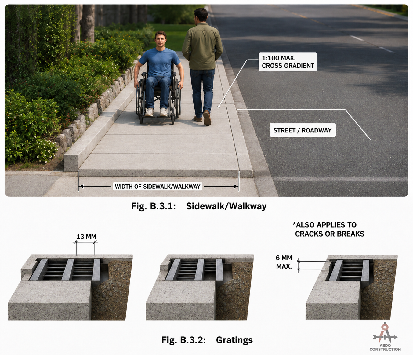
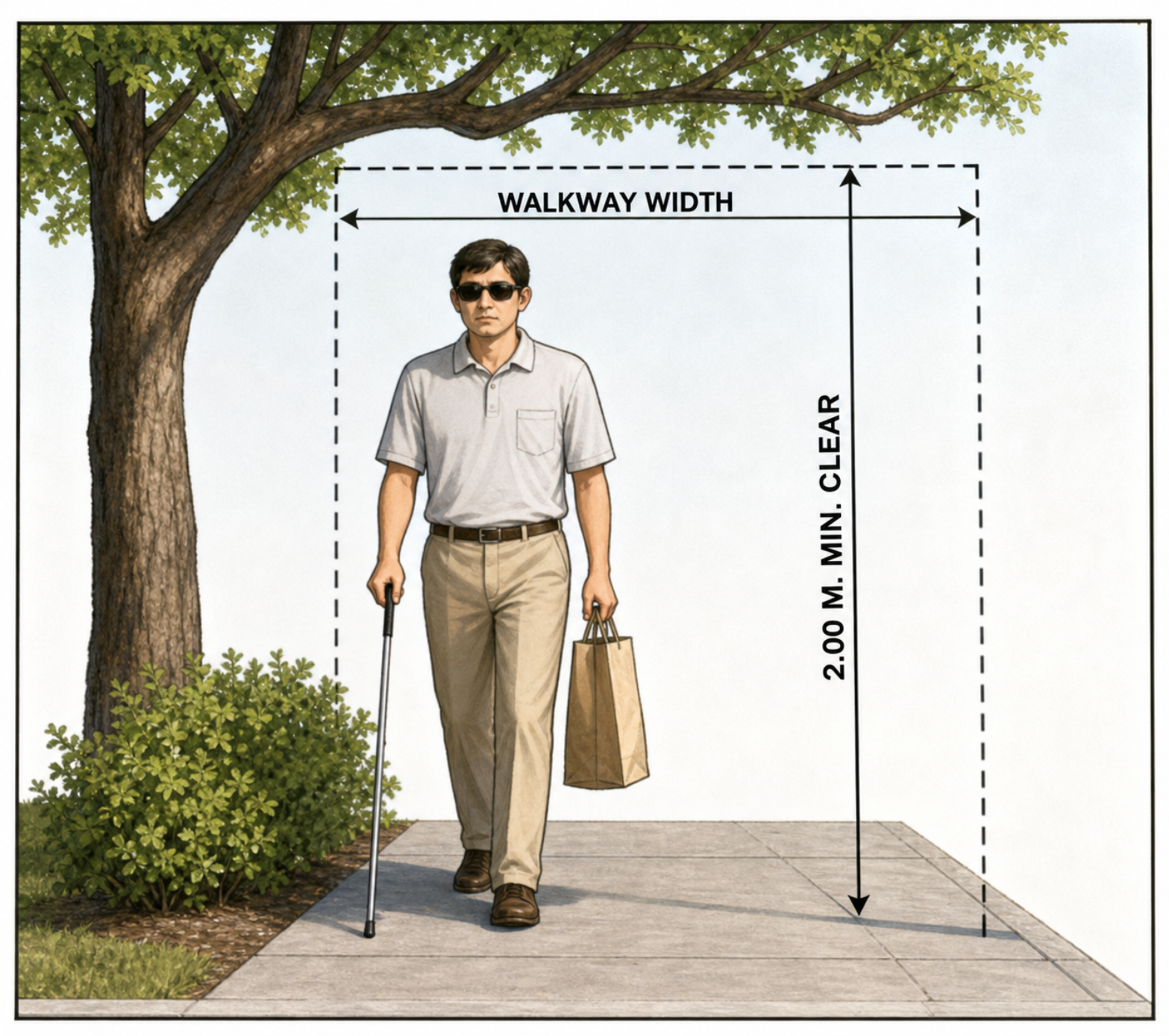
Walkways & Tactile Paving
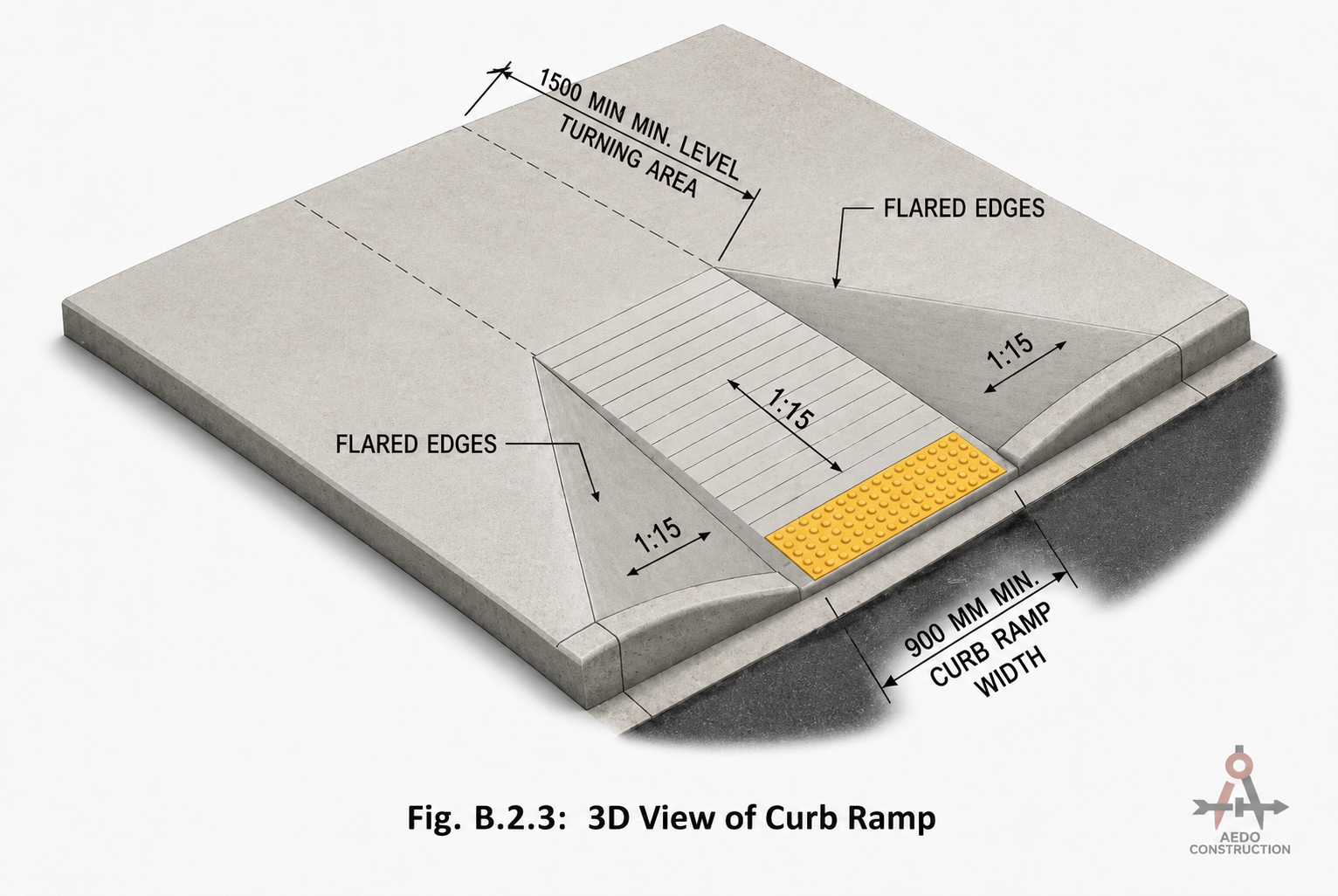
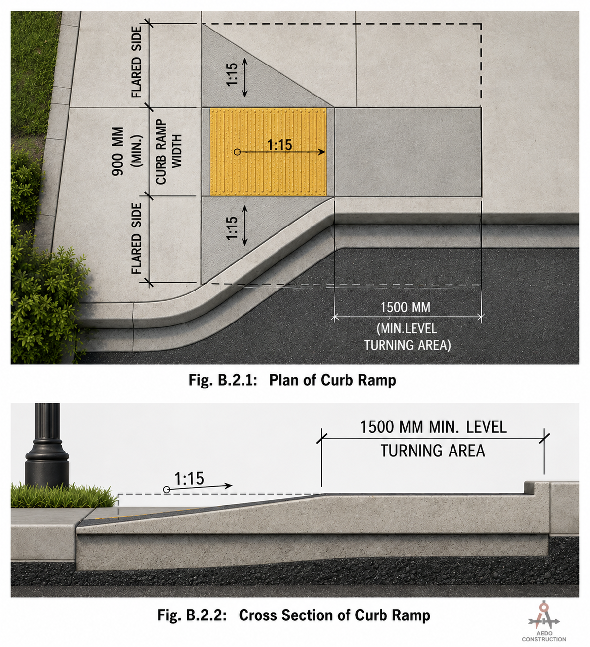
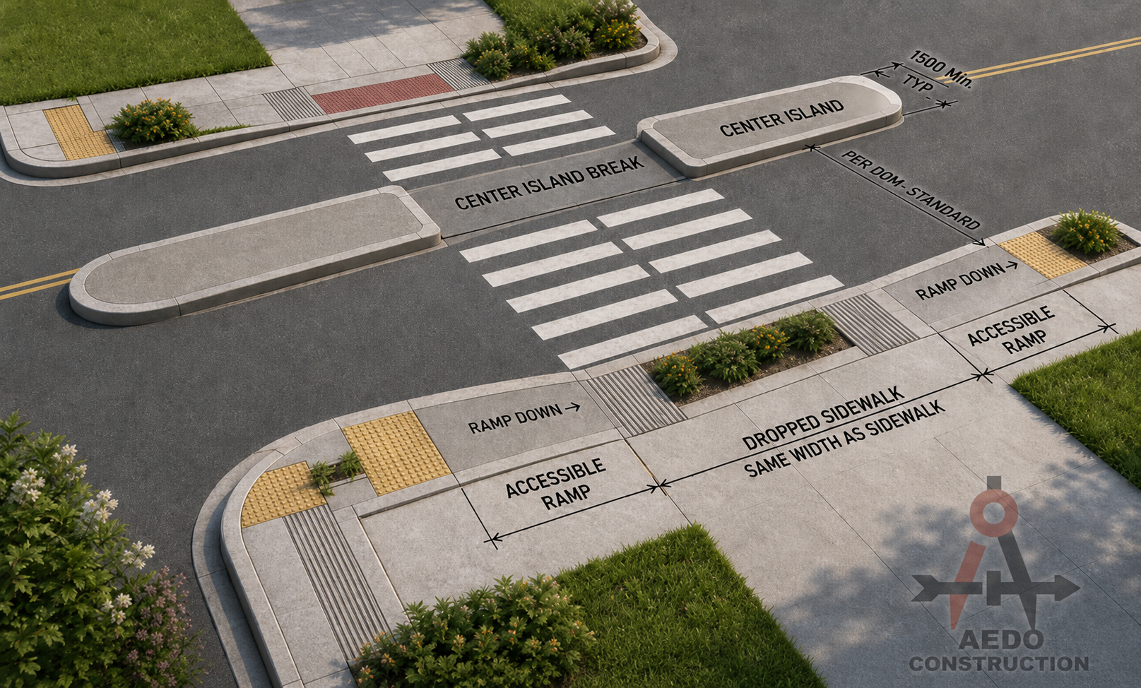
Curb Ramps
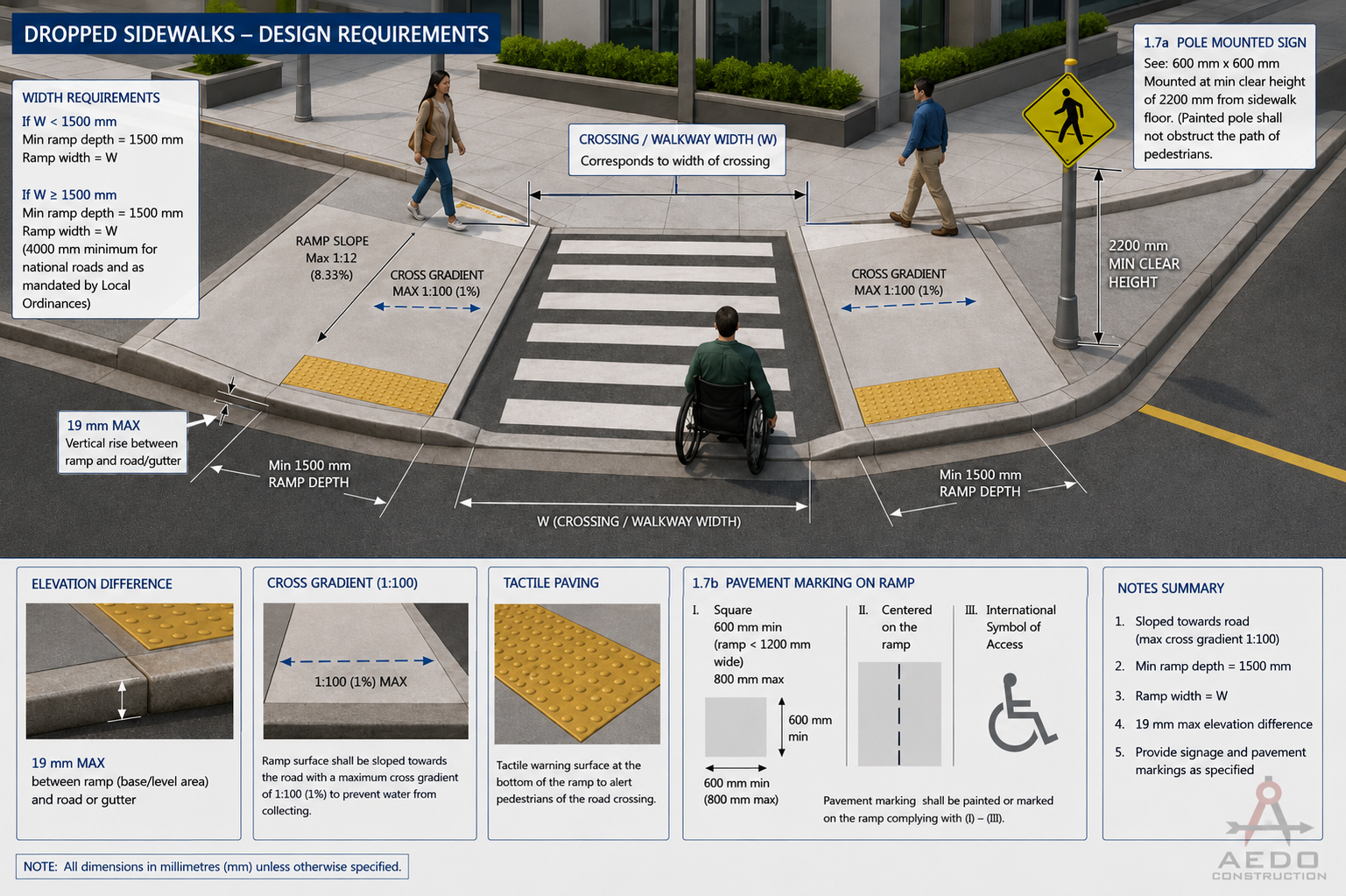
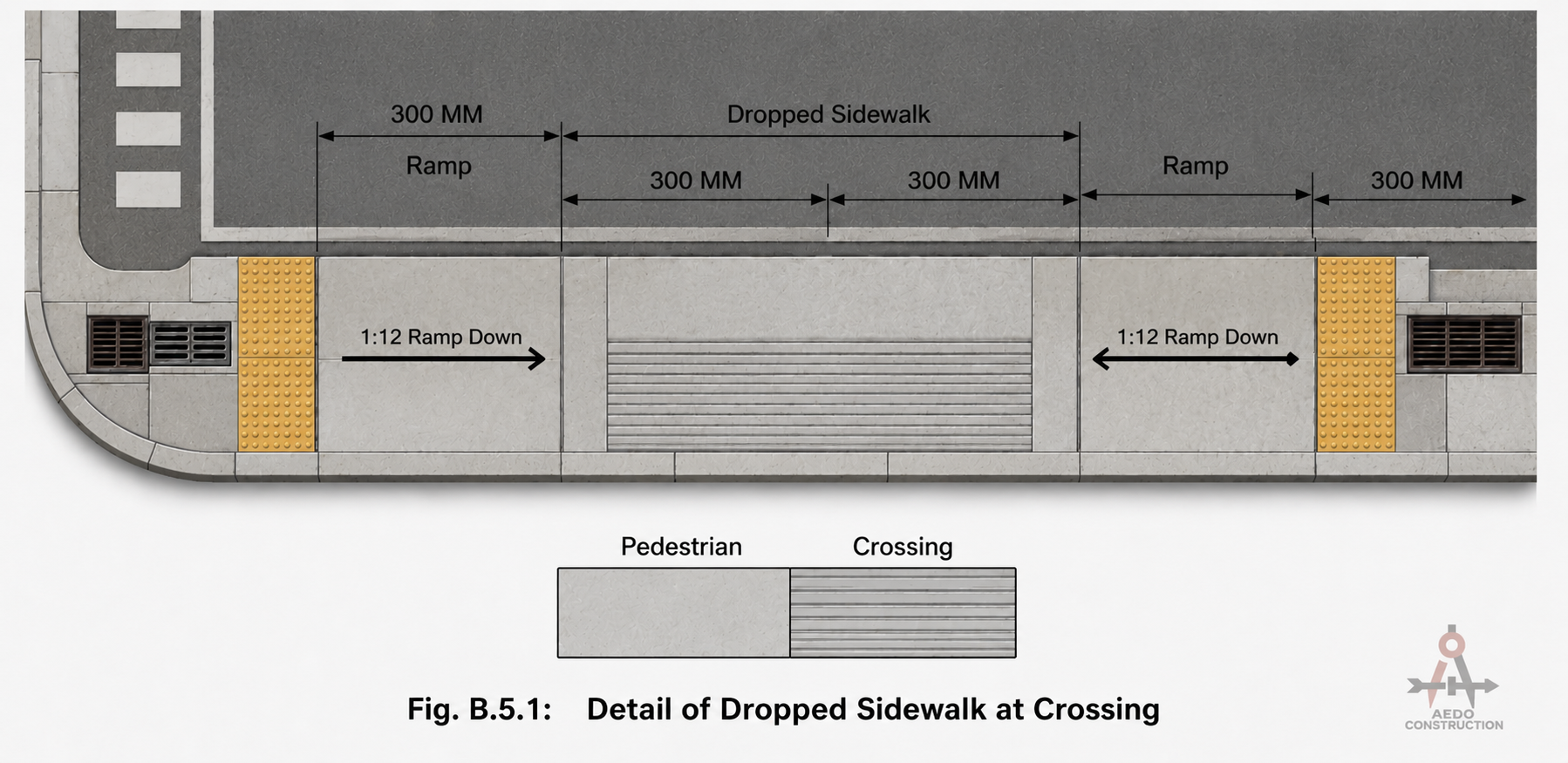
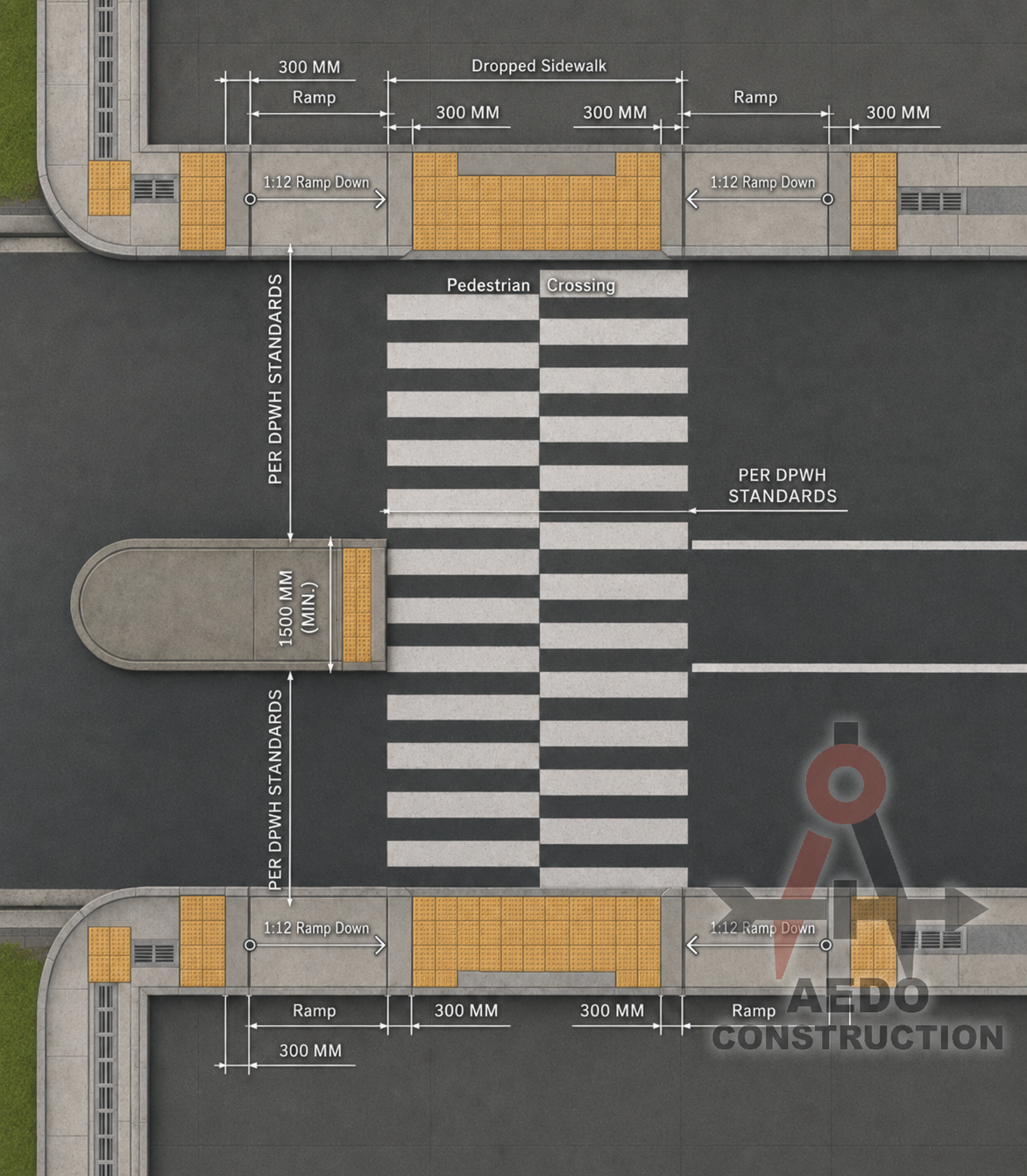
Dropped Sidewalks
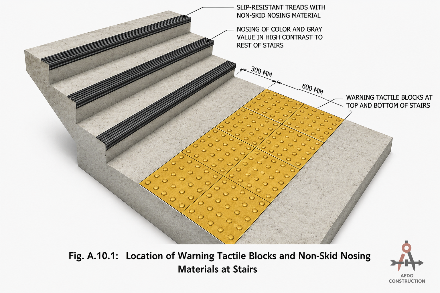
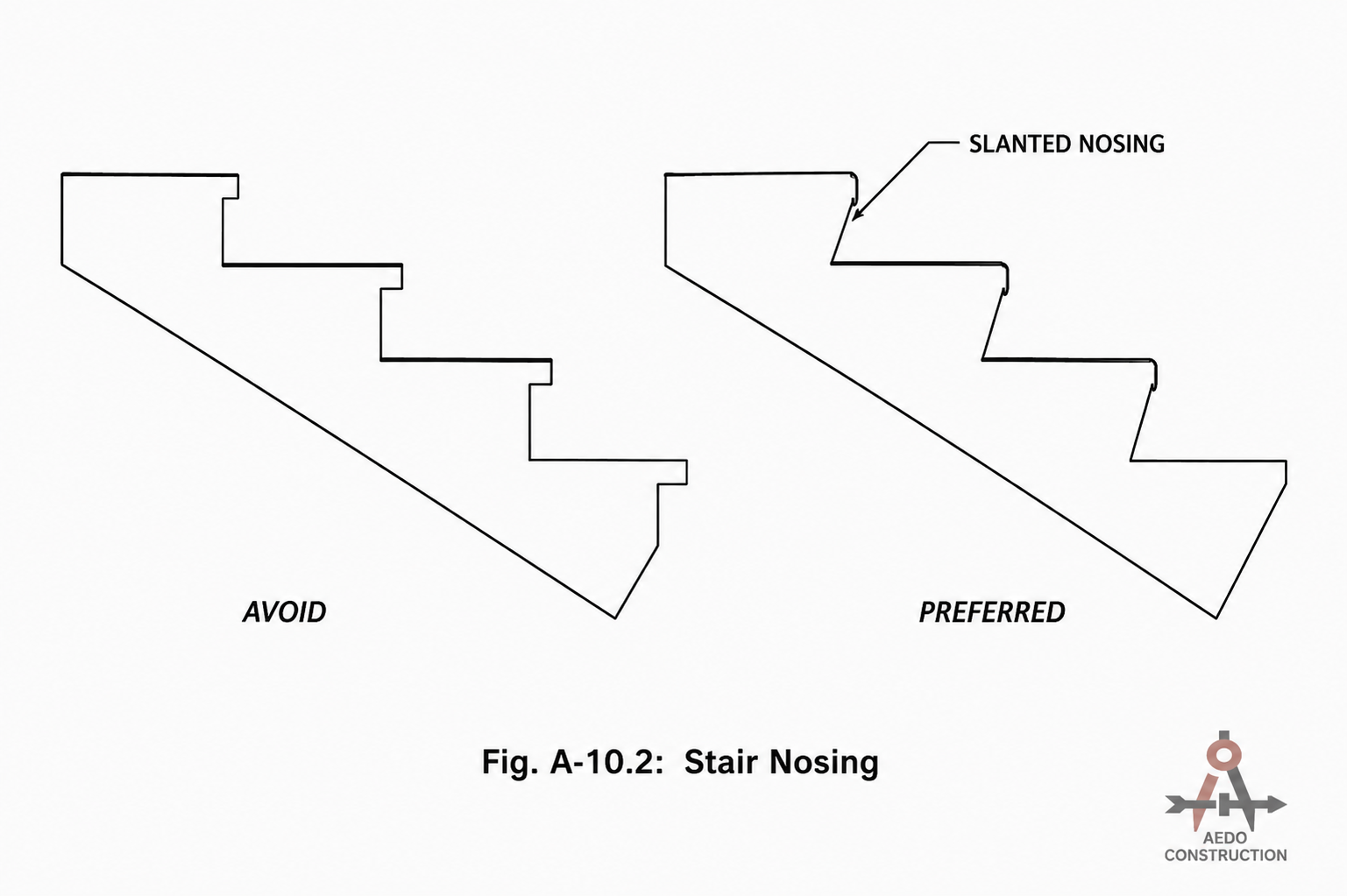
Stairs & Stair Nosing
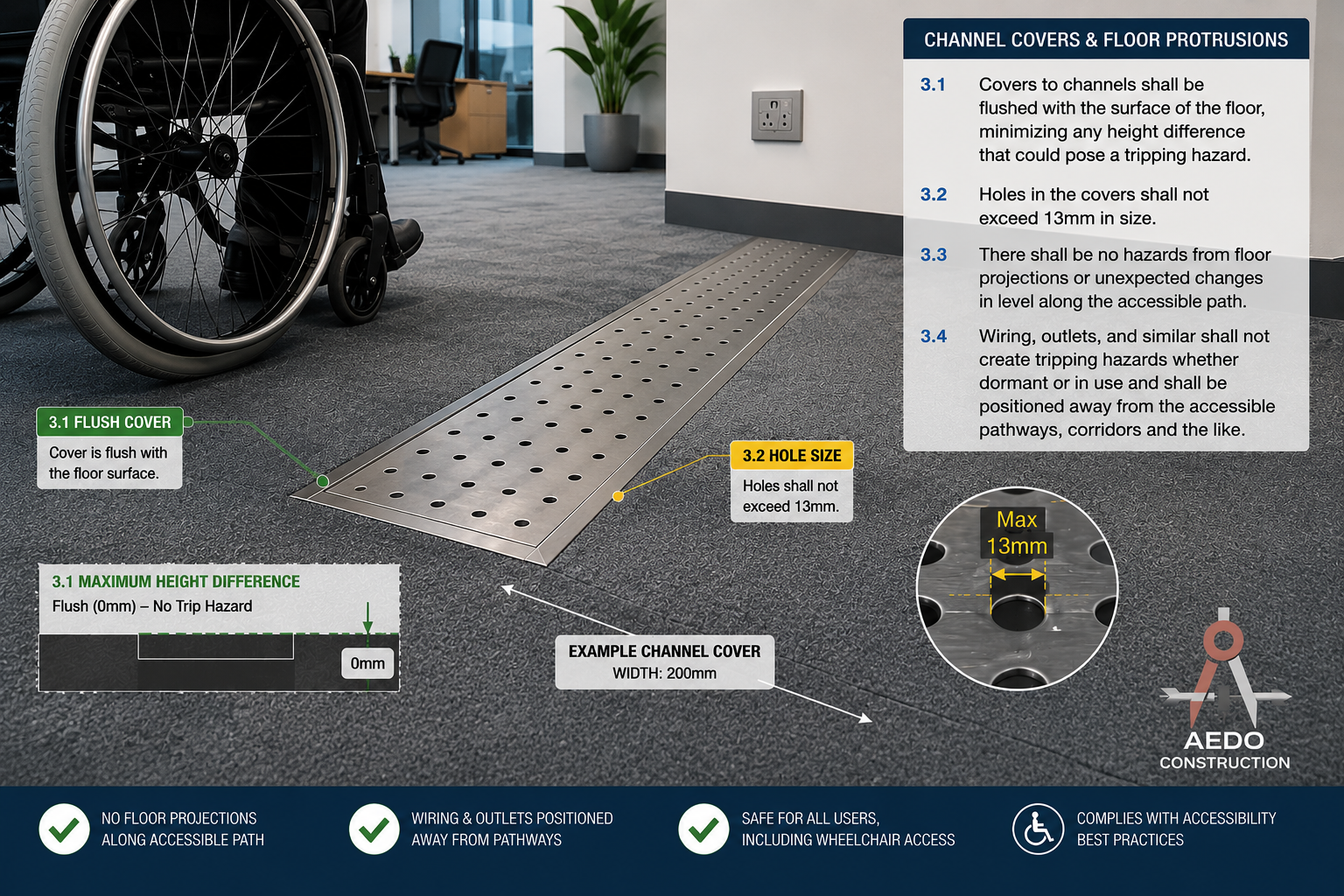
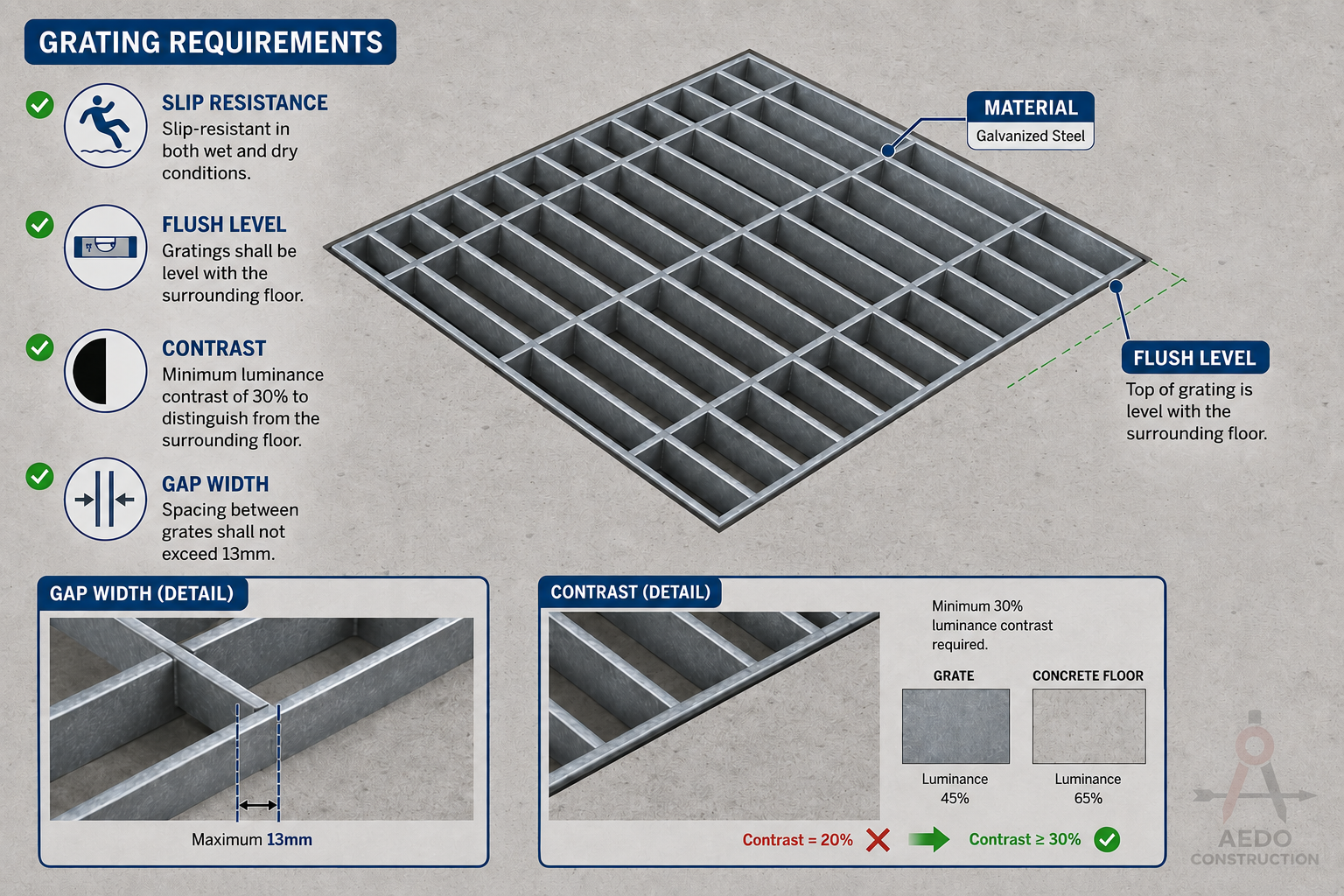
Floor Surfaces
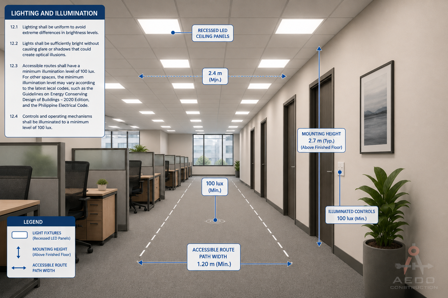
Lighting & Illumination
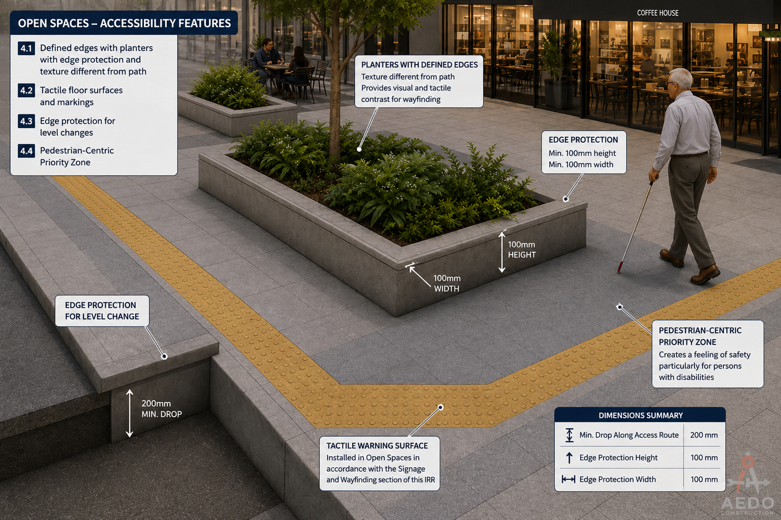
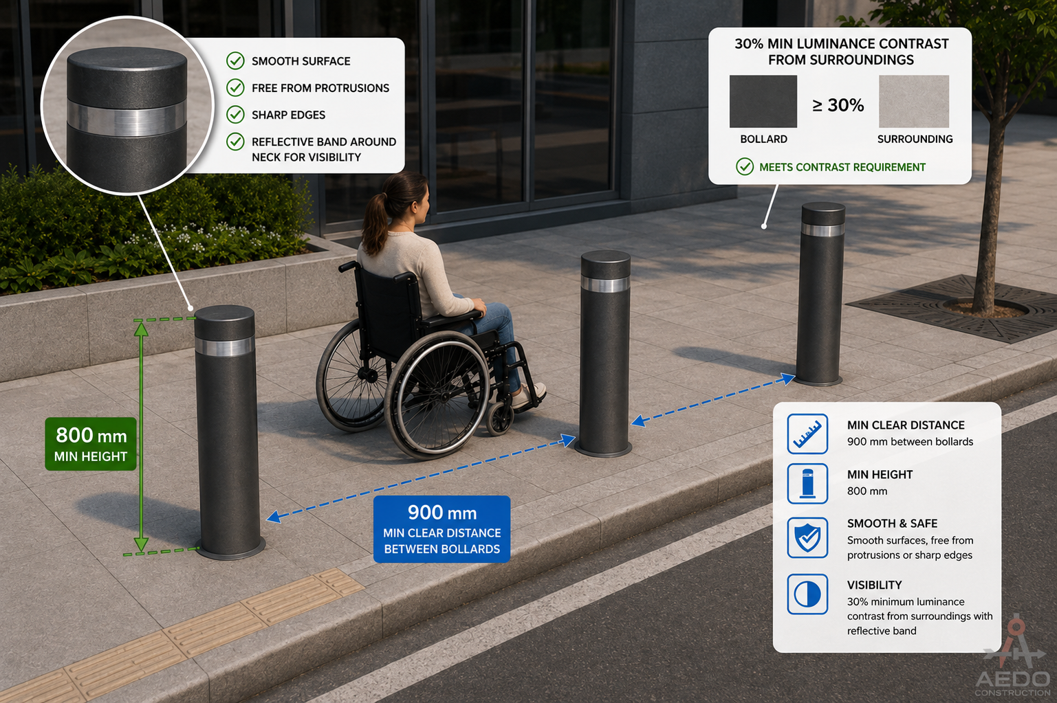
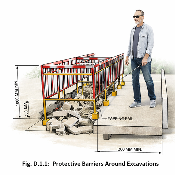
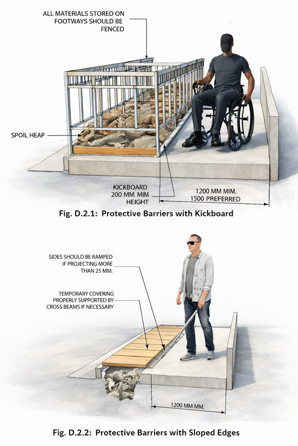
Open Spaces & Bollards
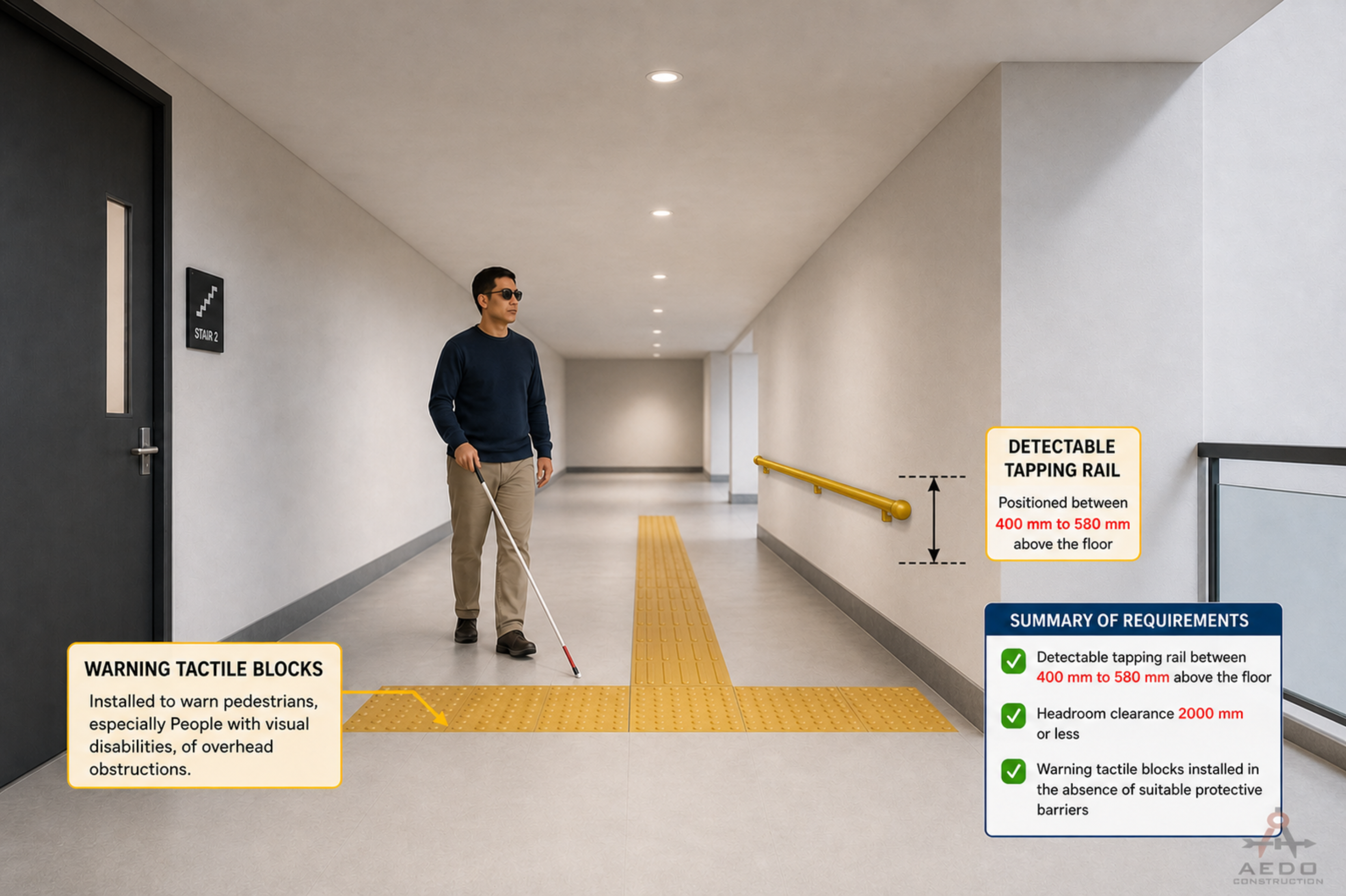
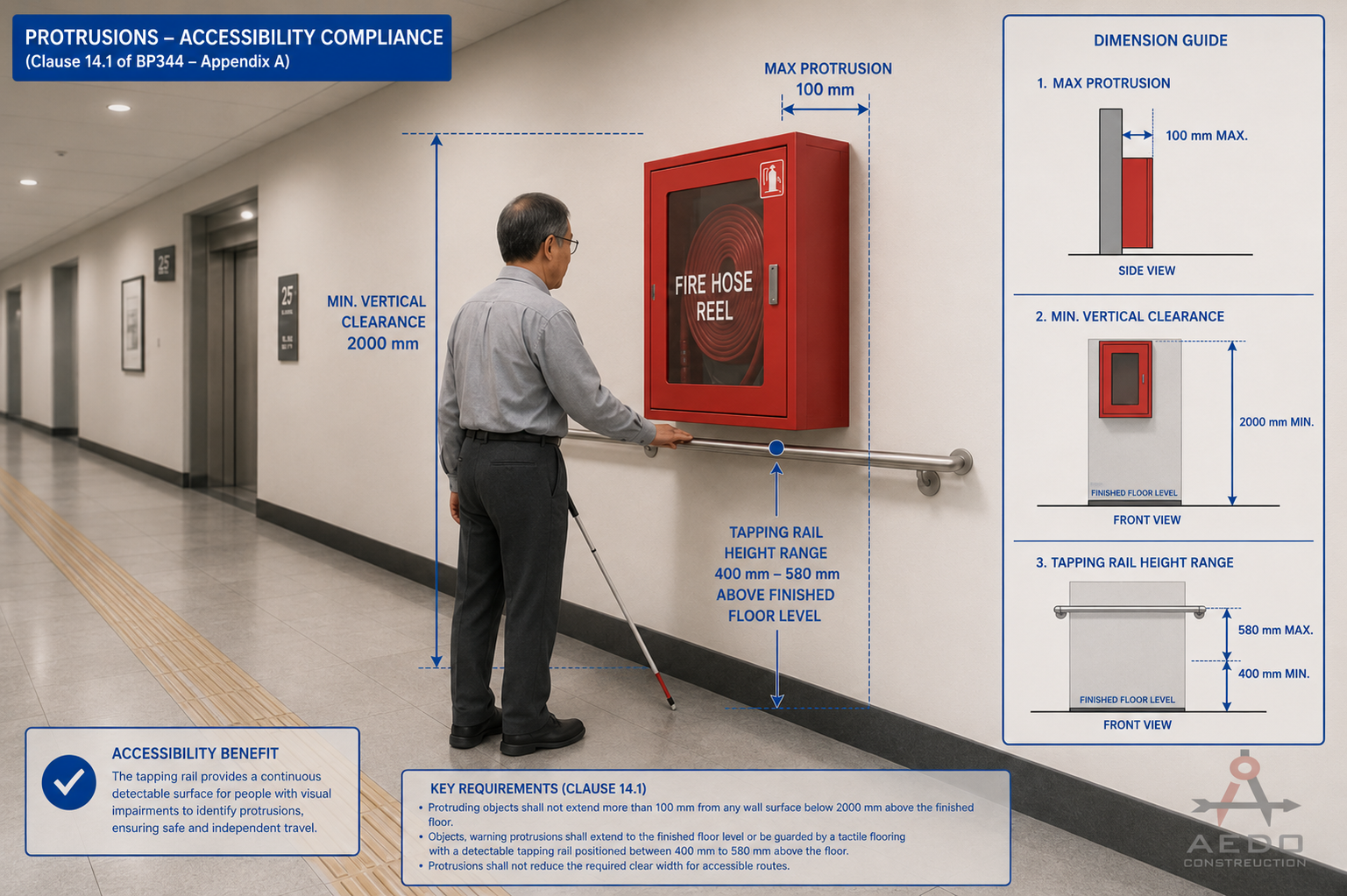
Overhead Hazards & Protrusions
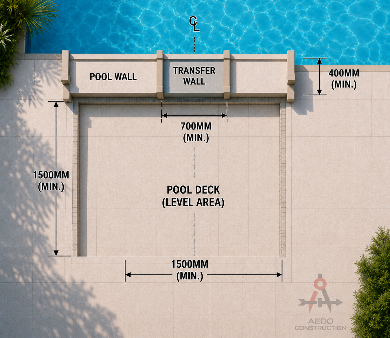
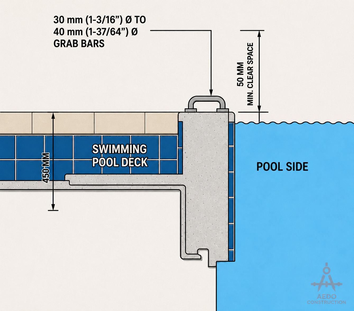
Swimming Pools
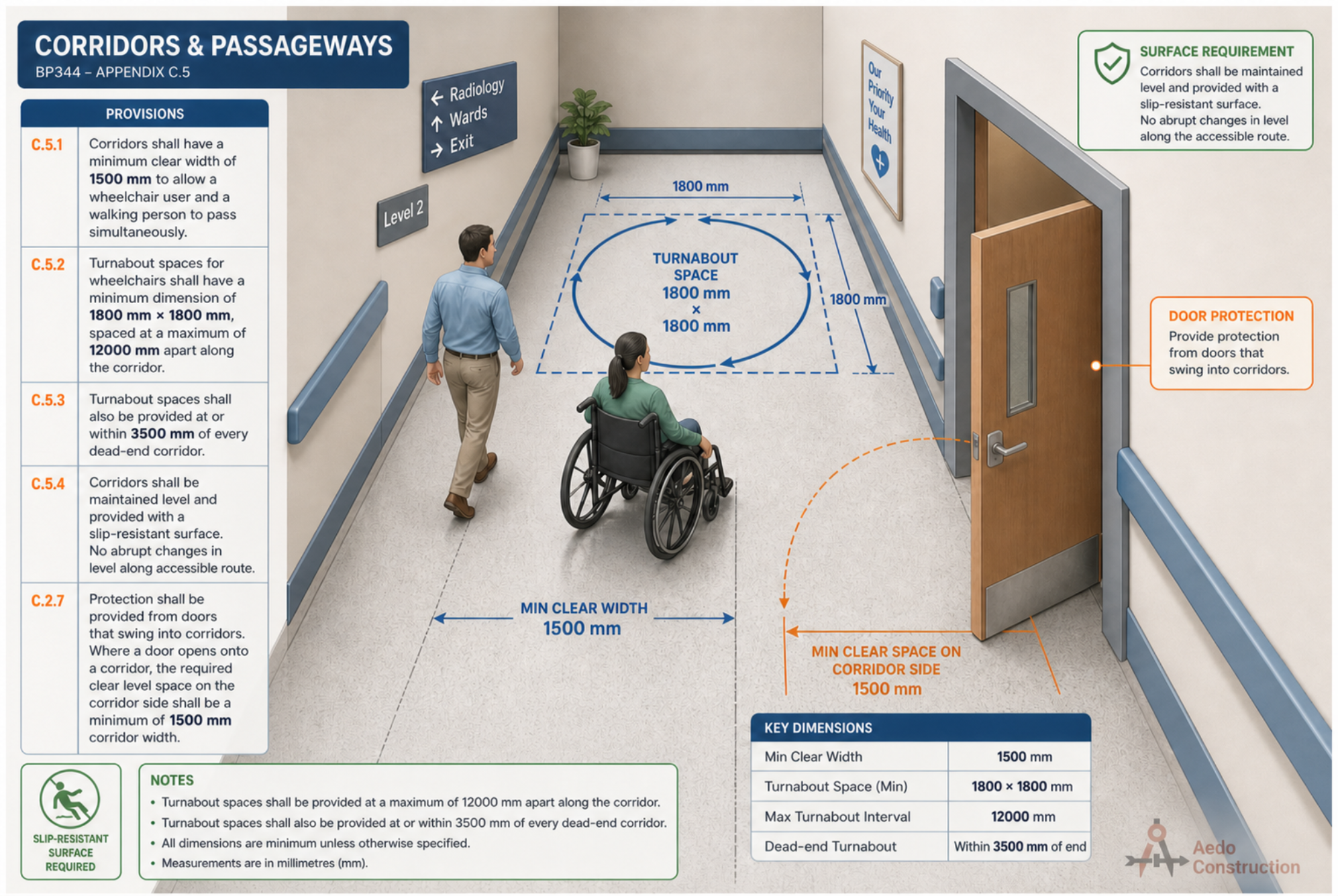
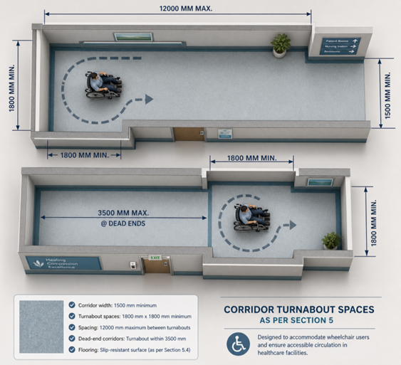
Corridors & Passageways
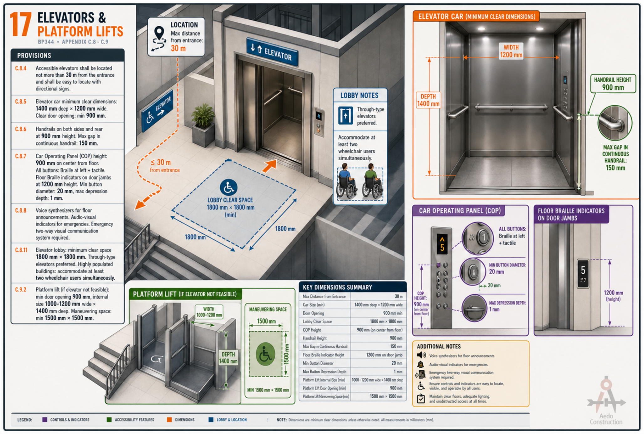
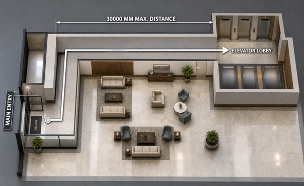
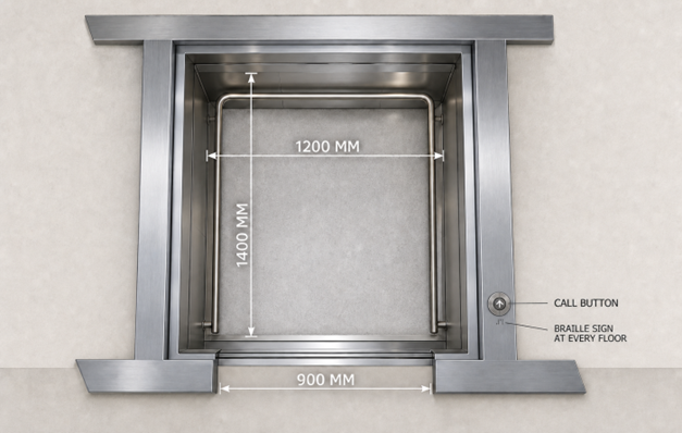
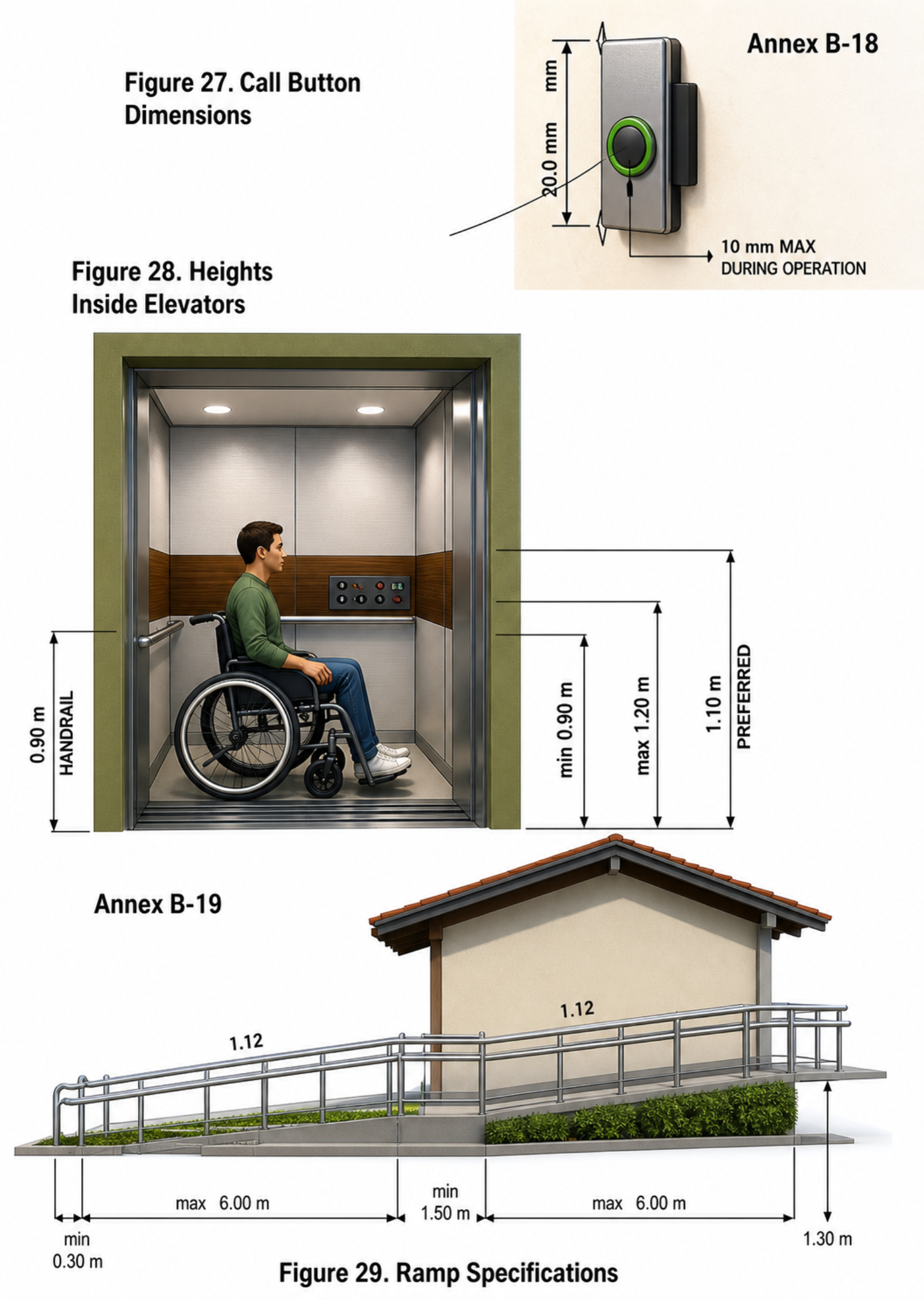
Elevators & Platform Lifts
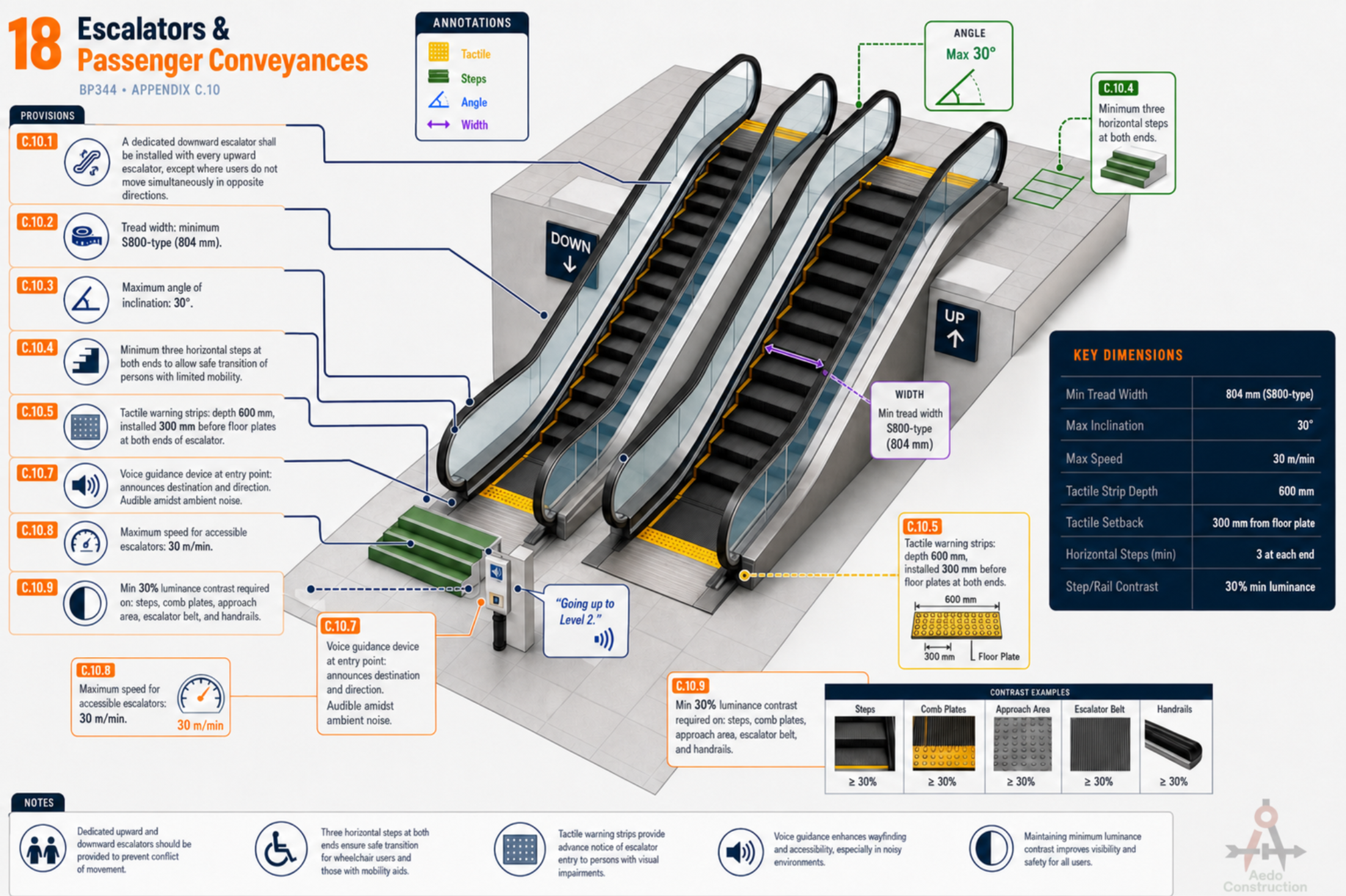
Escalators & Passenger Conveyances
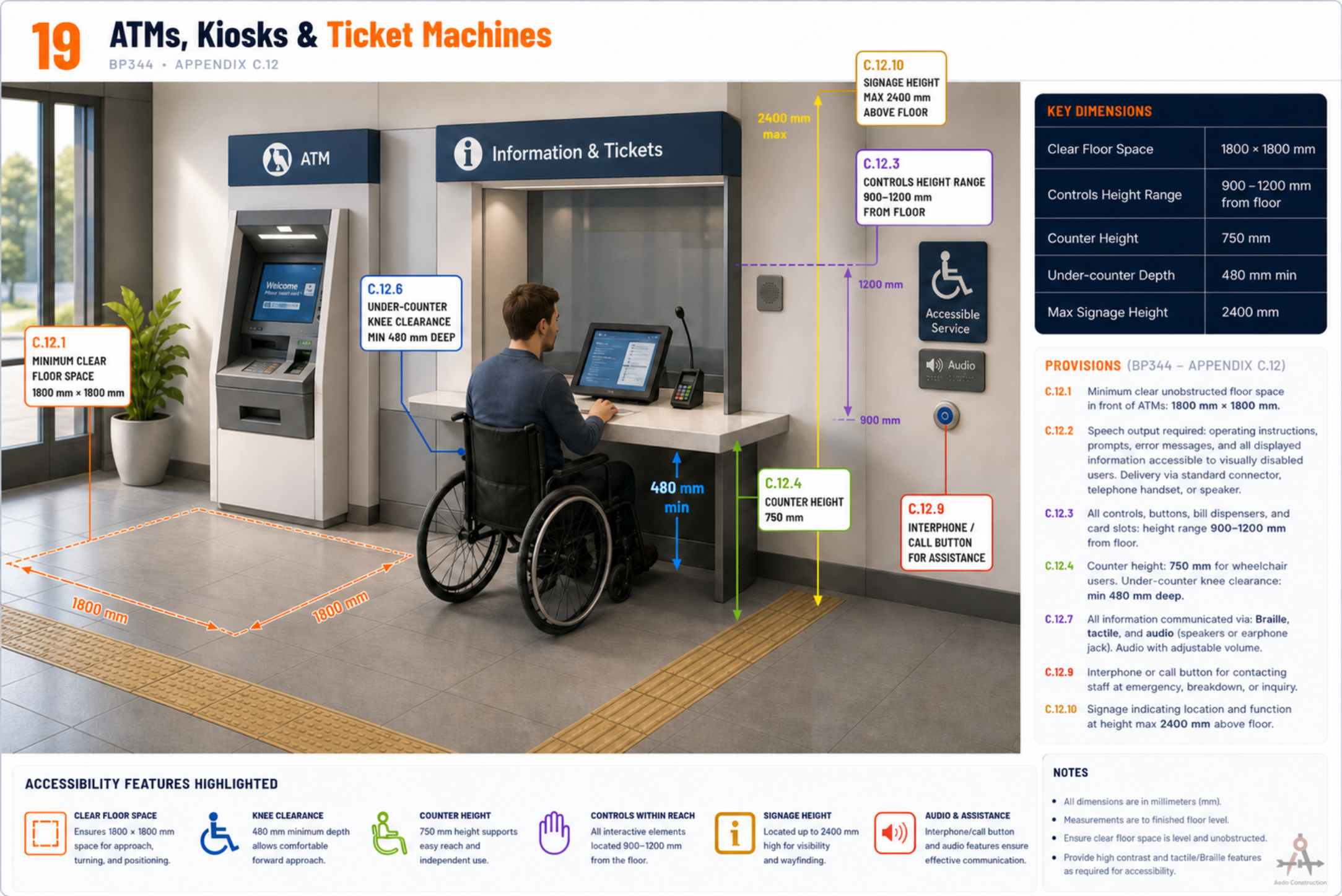
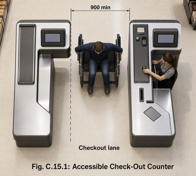
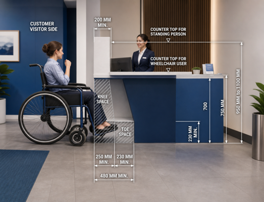
ATMs, Kiosks & Ticket Machines
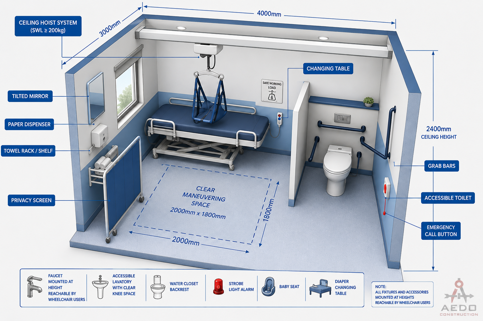
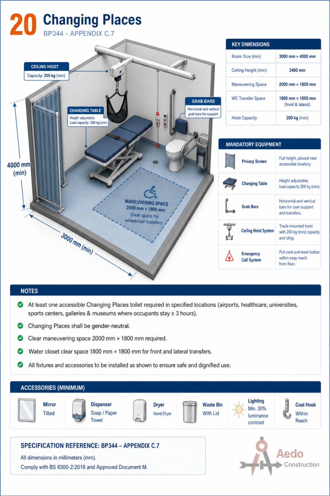
Changing Places
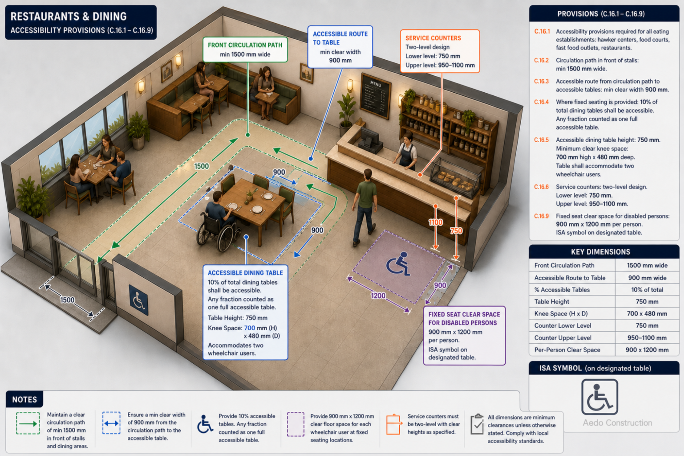
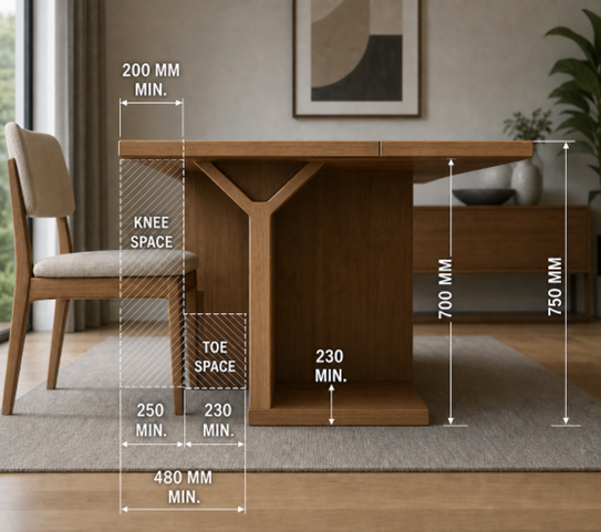
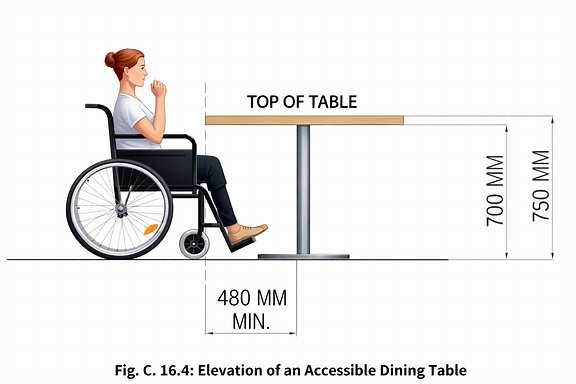
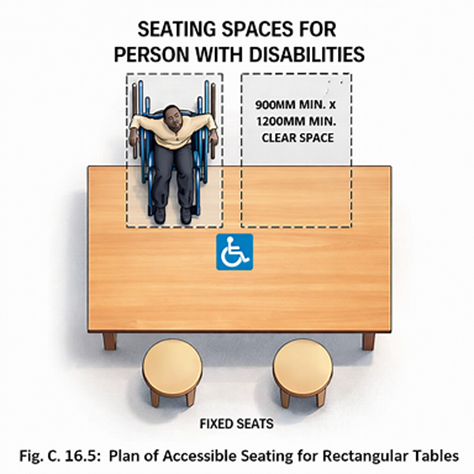
Restaurants & Dining
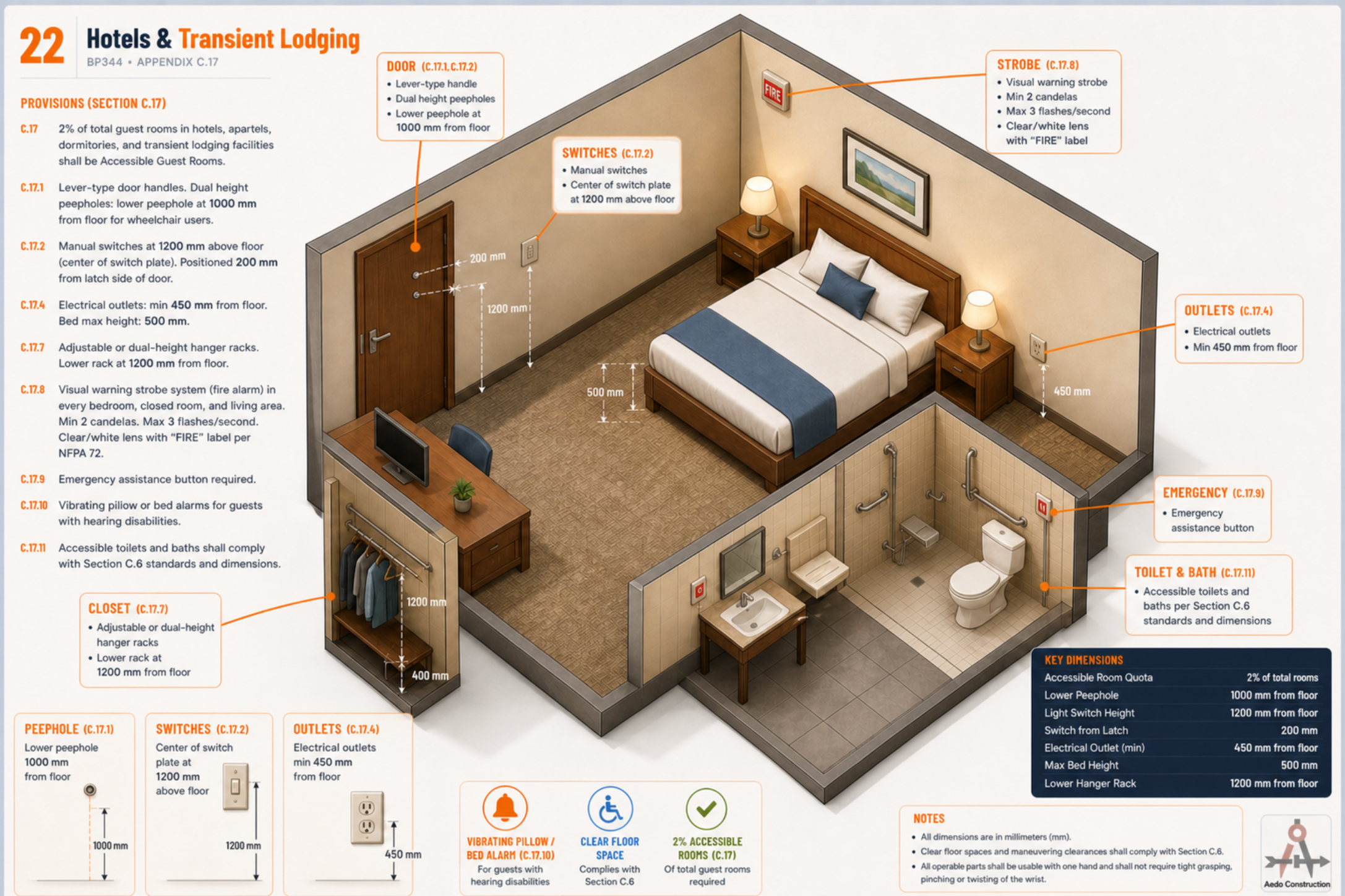
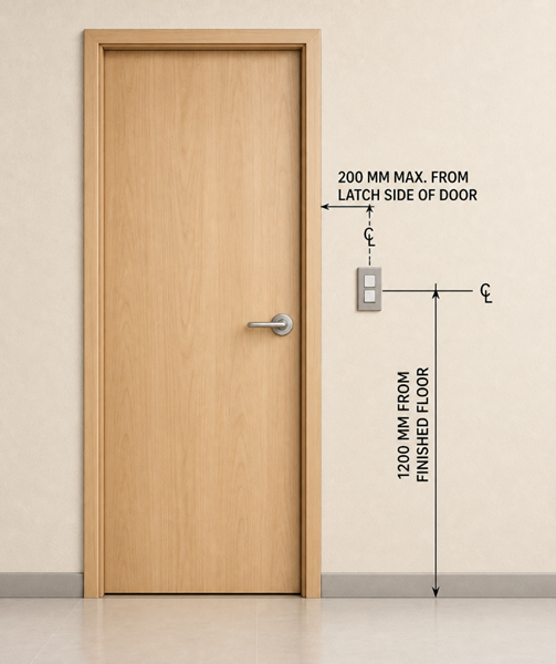
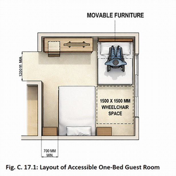
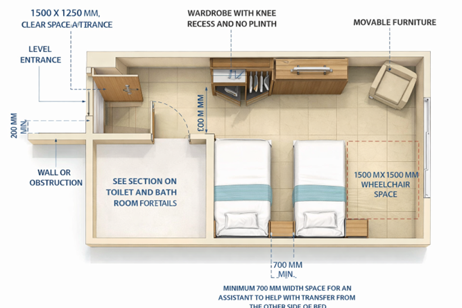
Hotels & Transient Lodging
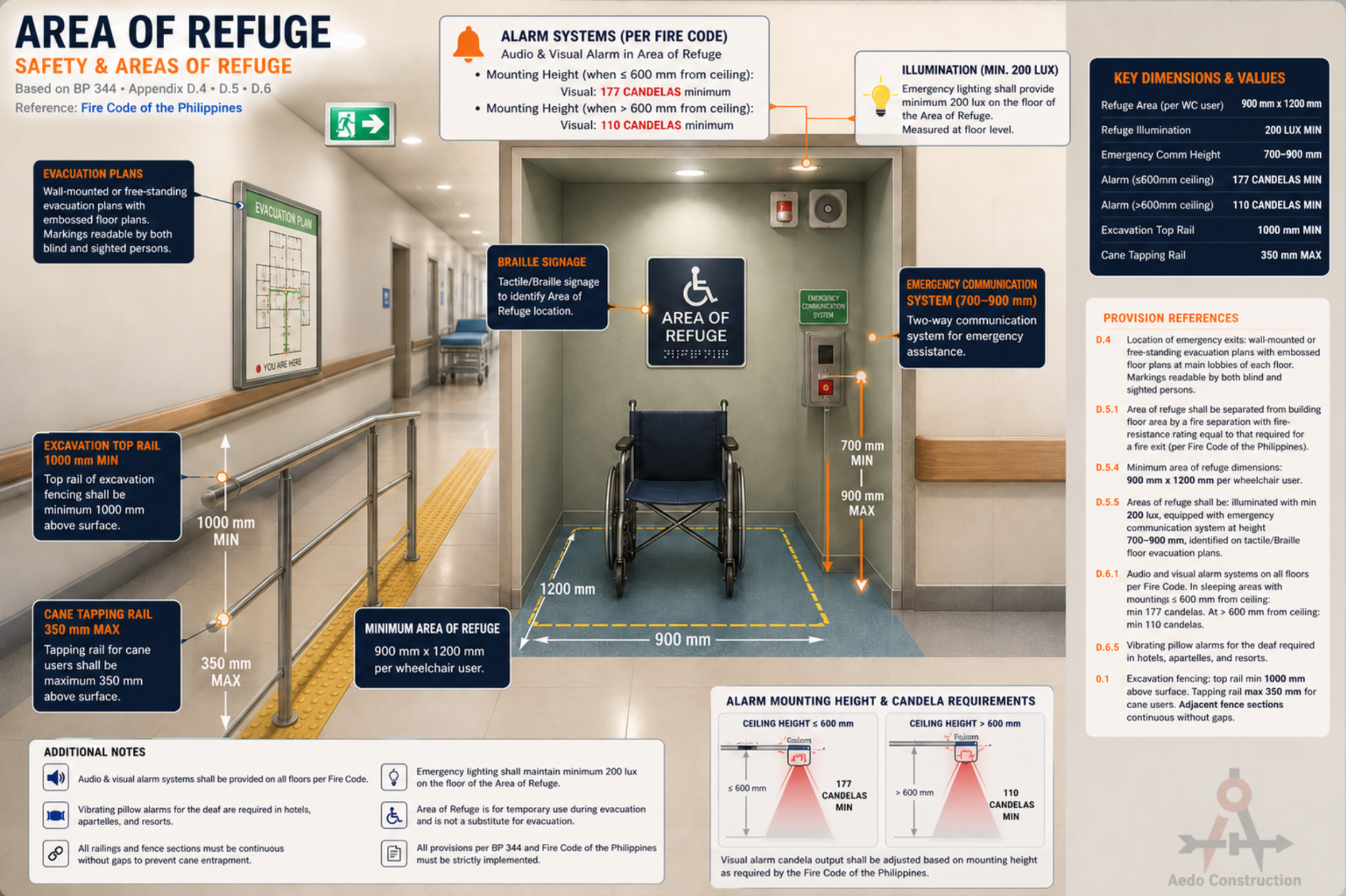
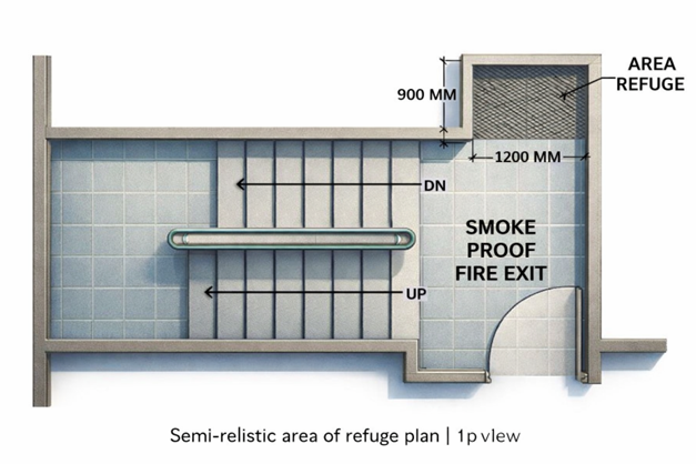
Safety & Areas of Refuge
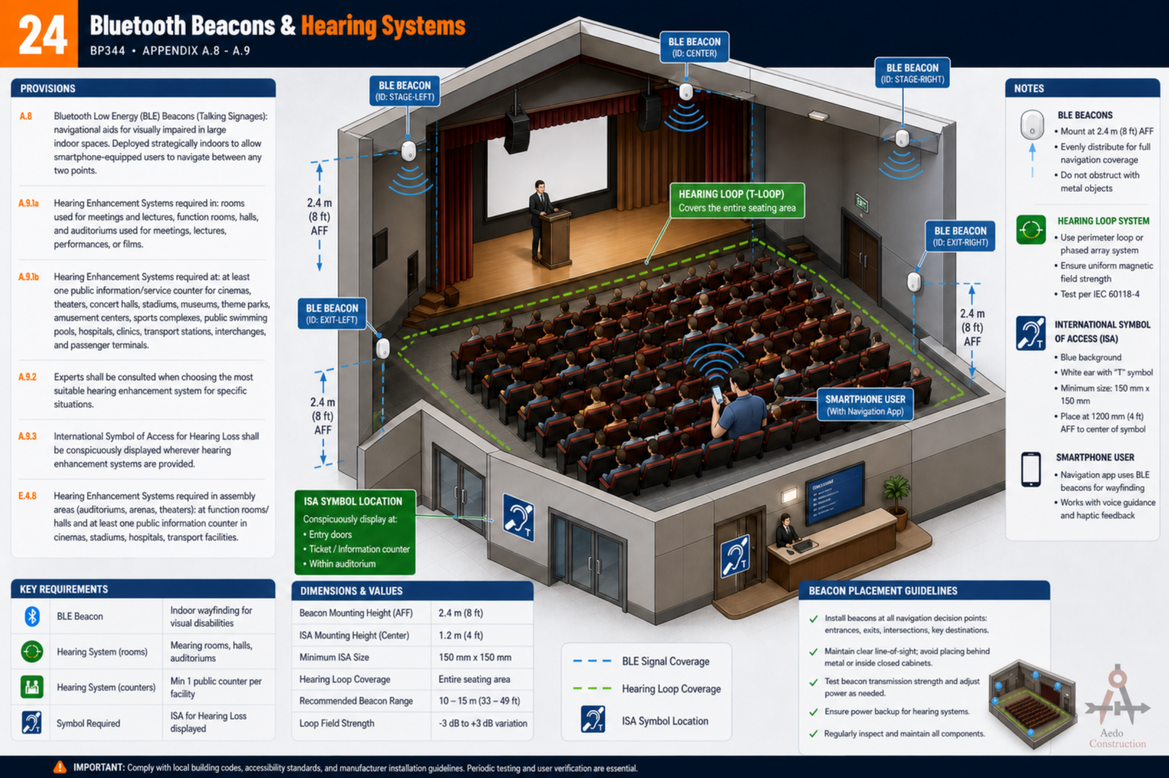
Bluetooth Beacons & Hearing Systems
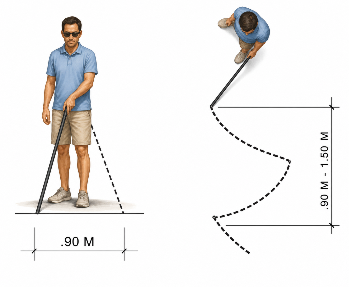
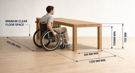
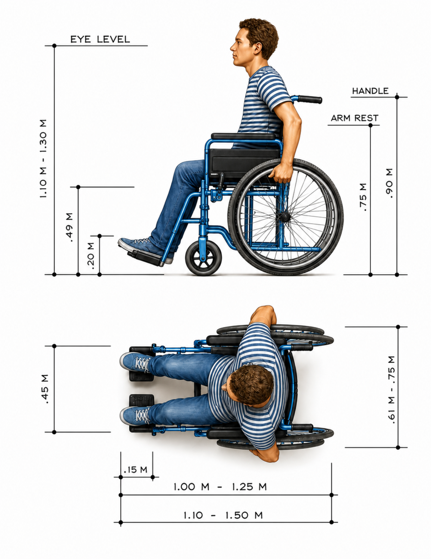
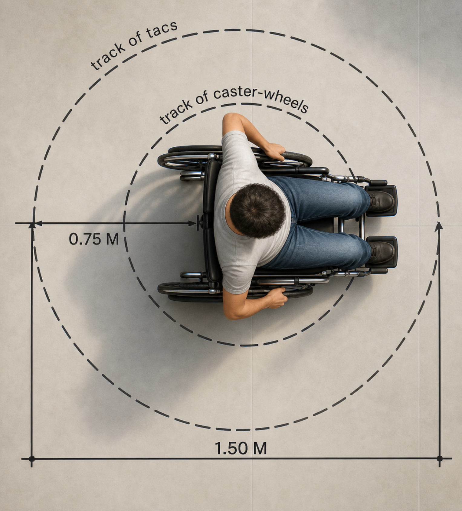
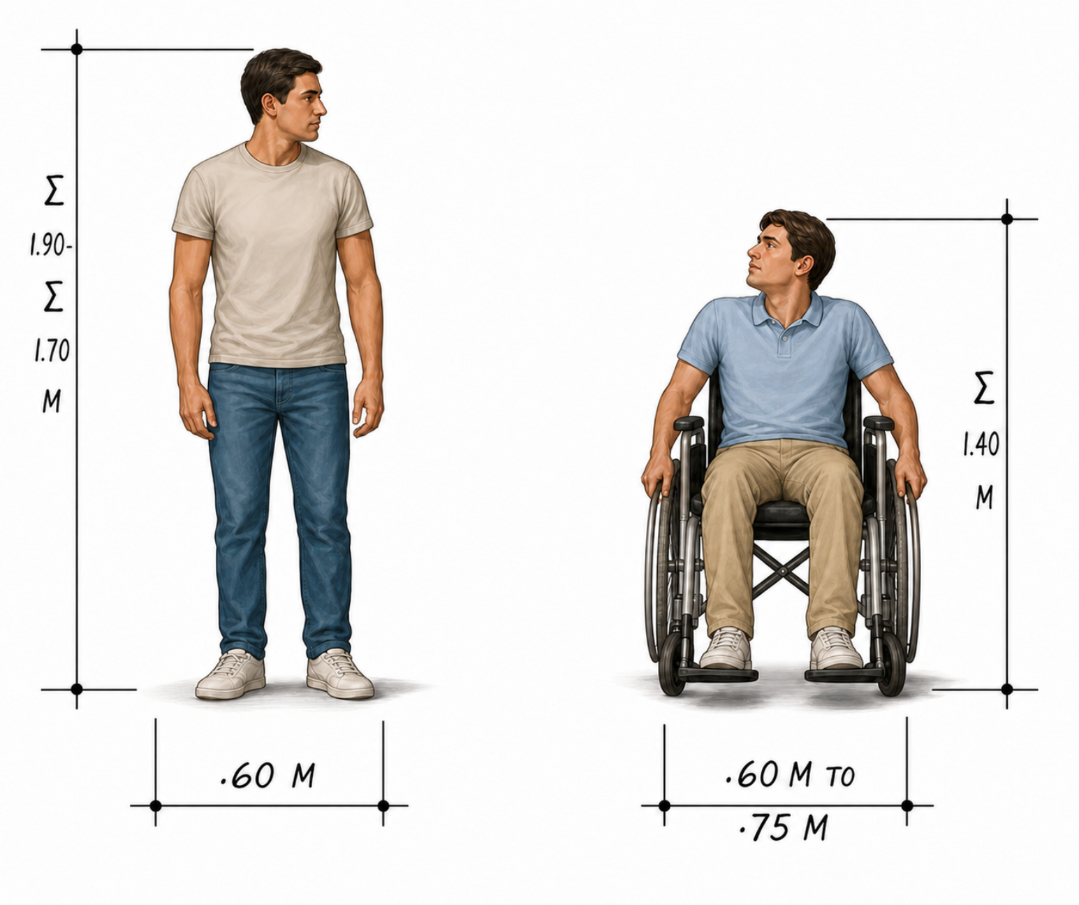
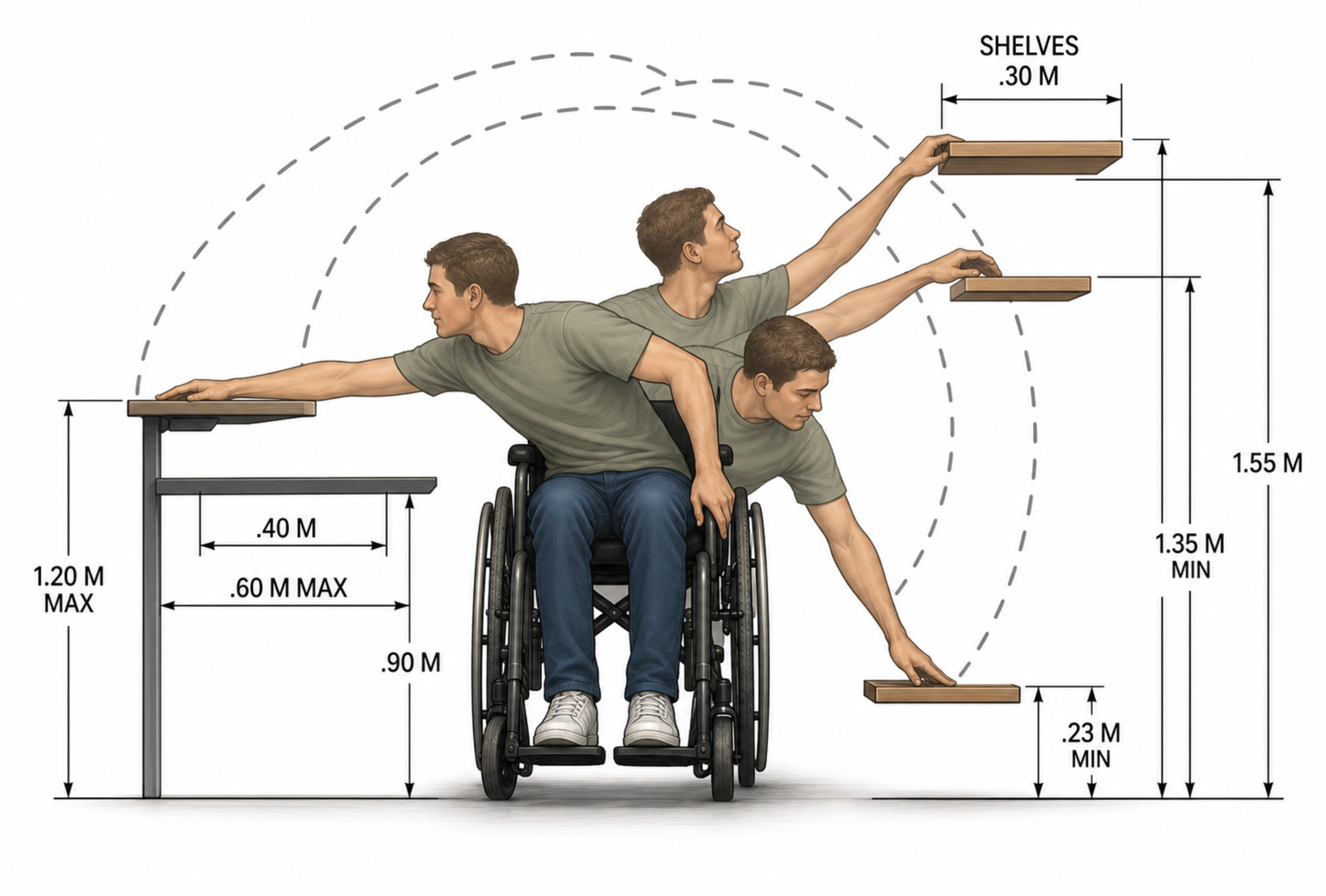
Wheelchair Dimensions & Clearances
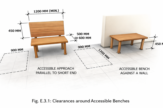
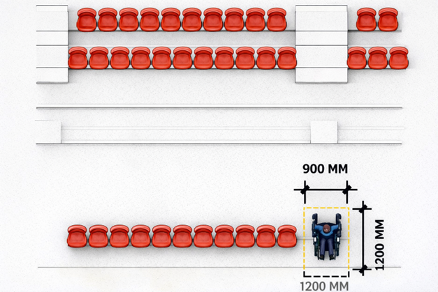
Accessible Seating & Benches
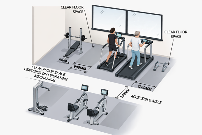
Recreation & Fitness Facilities
Beyond Compliance — We Actually Build
AEDO Construction doesn't just explain BP 344 standards. We apply them in actual projects — from planning to turnover.
From planning to actual construction — compliant, practical, and buildable.
Common BP 344 Mistakes in Construction
AEDO provides visual references and practical implementation guidance to help you avoid costly compliance mistakes.
Engineering Tools for Real Construction Workflows
AEDO Engineering Apps are built for Philippine construction — by engineers, for engineers, contractors, estimators, and project managers.
Why Professionals Use AEDO
Need Help With BP 344 Compliance?
Whether you're preparing permit documents, reviewing plans, designing accessibility features, managing construction projects, or checking compliance — AEDO can help simplify the process.
Need a structure that's code-compliant by design?
This BP344 reference is built and maintained by AEDO Construction OPC — a Philippine design-build firm where every drawing meets NSCP 2015, BP344, and the Fire Code before it ever reaches your site. Engineers, architects, and own-tool builders under one roof.
Design & Build · End-to-End
From blueprint to turnover — one accountable team, one contract, one fixed price.
Design Plans, Drawings & Specs
Architectural floor plans, structural drawings, and bill of quantities — drawn against current code from day one.
- Architectural floor plans
- Structural drawings (NSCP 2015 · AISC · ACI)
- Bill of quantities
Structural Analysis & Design
Rigorous engineering — value engineering, design optimization, and forensic investigation of existing structures.
- NSCP-compliant design
- Seismic & wind analysis
- Structural investigation
Construction & Management
Full-scope construction & project management for architectural, structural, and interior fit-out — delivered safely, on schedule.
- Architectural construction
- Structural works
- Interior fit-out
Mobile Tools for the Field
Purpose-built Android apps used by engineers, contractors, and students nationwide.
Full NSCP 2015 reference: minimum design loads, wind calculator (§207A-207B), seismic base shear (§208), concrete, steel & foundation design — all in your pocket.
Estimate construction unit costs with editable material, labor, equipment & productivity rates. 10+ activities from excavation to gates — calibrated to local Philippine market prices.